MA-5002VZ Service Manual
5-10 Maintenance
130446-1 Rev. A
©2000 Crown International, Inc.
Type of Test Input Signal and Comments
or Adjustment Load Parameters
Turn the amplifier on after being off at least 10 sec-
onds. Observe that the ODEP lights come on after
about 4 seconds. The SPI/IOC lights should go off (if
on during delay) at this time. Input a 1-kHz 2 Vrms
sine wave into each channel and observe that the SPI/
IOC lights are on bright. Turn down the input level to
about 0.5 Vrms and observe that the SPI/IOC lights
remain on, but dimly. Remove the input signal and
load the amplifier to 8 ohms/Ch. Insert the 0.5 Vrms
signal again and note that the ILOAD/ILIMIT indicators
come on green. Change the load to 1 ohm/Ch, switch
to a square wave (20% Duty Cycle), and increase in-
put level to 2 Vrms. Note that the ILOAD/ILIMIT indicators
turn red. This check also constitutes the Current Limit
Check.
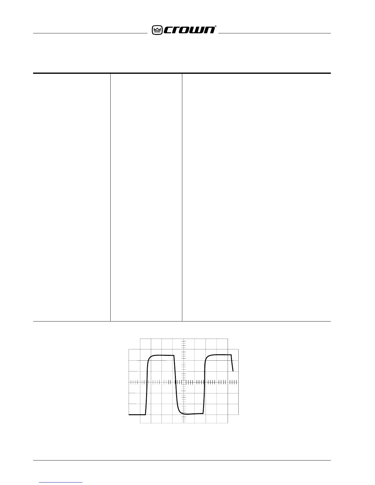
With an 8-ohm load on each channel, insert a 10-kHz
square wave and adjust amplitude to produce an
output 10V below clipping (see Figure 5.3). Observe
a 30V/µS (or higher) slew rate. The output waveform
should be stable with no ringing or over-shoot.
Insert a 5Vpp 4-Hz square wave with an 8-ohm load
on the output. The protection relay should cycle.
19. LED Check, 1-kHz Sine/Sq Wave
Current Limit Check Various Loads
20. 10 kHz Square Wave 10-kHz Sq. Wave
Slew Rate Test 8 ohm Load
21. DC/LF Protect 4-Hz Sq. Wave
8-ohm Load
Figure 5.3 10-kHz Square Wave

 Loading...


