MA-5002VZ Service Manual
5-12 Maintenance
130446-1 Rev. A
©2000 Crown International, Inc.
Type of Test Input Signal and Comments
or Adjustment Load Parameters
Next configure the amp for parallel mono operation.
With the input signal now present on channel one only,
load channel one output with 8 ohms and channel
two with 2 ohms. Observe that channel two ODEP
protection circuit is limiting both channel one and
channel two outputs. Next load channel one with 2
ohms and channel two with 8 ohms. Observe that
channel one ODEP protection circuit is limiting both
channel one and channel two outputs.
Return the cooling fan blade to normal operation af-
ter these tests have been completed, and allow a few
minutes for the amplifier to cool with no signal input.
Return all controls to initial conditions per Section
5.4.1.
Correct operation of the ODEP circuit is dependent
upon correct ODEP null settings (Step 6).
Place the sensitivity switches in the 26 dB position.
Use a 60-Hz/7-kHz (standard SMPTE IM signal) input
signal summed in a 4:1 ratio. Set the 60-Hz portion
for 73.8 Vrms at the output of the channel under test.
This is your 0 dB reference. Measure the I.M. distor-
tion. Check in –5 dB (power) steps until –35 dB is
reached (range is 1,065 W down to 0.34 W). Read-
ings should be less than .05% at each level.
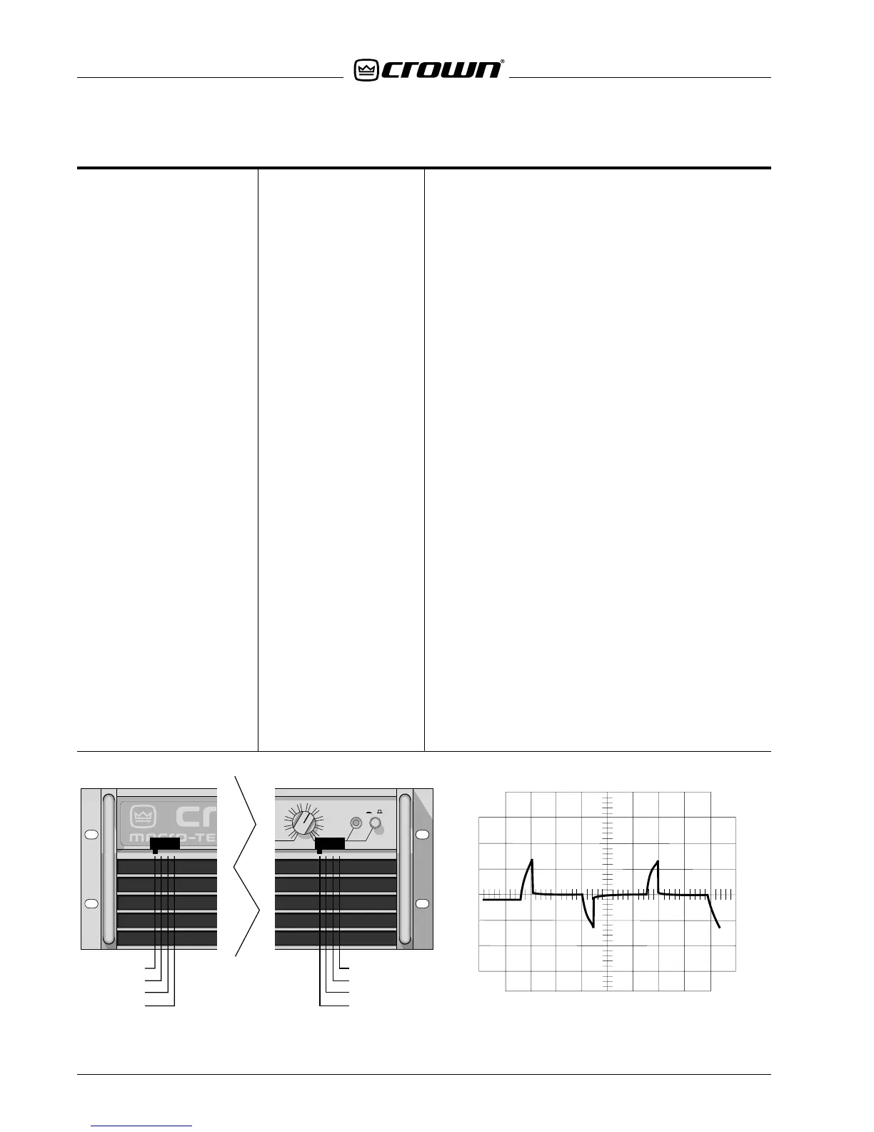
24. Intermodulation I.M. Signal Source
Distortion (I.M.D.) 8-ohm Load
Figure 5.5 ODEP Protection
ENABLECH2
l
0
30
27
24
18
15
9
6
3
0
LEVEL
21
12
VZ-ODEP
LOCK LOW
VZ (AUTO)
VZ (AUTO)*
VZ (AUTO)*
VZ (AUTO)
LOCK LOW
VZ-ODEP
CH 1 VZ MODE SWITCH CH 2 VZ MODE SWITCH
*On Original Control Module
Q42930-0 this was the
LOCK HIGH position.
Figure 5.4 VZ Mode Switch Locations

 Loading...


