Chapter 2. Installation
19
May 2011
Chapter 2. Installation
2.1 General
This chapter provides detailed instructions for mechanical installation of the ETU-01A.
Following the completion of installation, please refer to Chapter 3 for operating information.
2.2 Site Preparation
Install the ETU-01A within reach of an easily accessible grounded AC or DC (48V) outlet.
The outlet should be capable of furnishing 90 ~ 250 VAC or 18VDC to 72VDC for DC model unit.
The AD model supports AC plus DC power simultaneously for redundant 1+1 power operation.
Allow at least 10 cm (4 inch) clearance at the rear of the ETU-01A for power, signal lines and
interface cables.
2.3 Mechanical Assembly
The ETU-01A is designed for tabletop or bench installation, and is delivered completely
assembled. No provision has been made for bolting the ETU-01A to a tabletop. An optional 19"
rack mount adapter is available.
2.4 Electrical Installation
2.4.1 Power connection
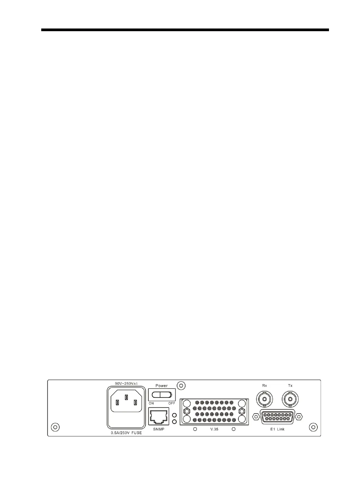
AC power is supplied to the ETU-01A through a standard (IEC C14) 3-prong plug. (Refer to
Figure 2-1) The ETU-01A should always be grounded through the protective earth lead of the
power cable.
The line fuse is located in an integral-type fuse holder on the rear panel. Make sure that only
fuses of the required rating are used for replacement. Do not use repaired fuses or short-circuit the
fuse holder. Always disconnect the power cable before removing or replacing the fuse.
DC power is supplied to the ETU-01A through a three pin terminal block. (Refer to Figure 2-
2) The ETU-01A should always be grounded through the 'Frame Ground' terminal in DC
applications.
2.4.2 Rear panel connectors
Please refer to the User Data Channels table on page 10 for a description of the digital
interface connectors located on the rear panel of the ETU-01A (Refer to Figure 2-1). The E1 line
connectors incorporate DB15 pin (AT&T PUB 62411) for balanced 120 ohm connections on
twisted pair cable or two BNC Coax connectors for 75 ohm unbalanced connection on coaxial
cable. (Appendix A provides detailed information on the various interface modules and connectors).
Figure 2-1 ETU-01A AC rear panel, Option: DCE (V.35)
 Loading...