Chapter 2. Installation
20
May 2011
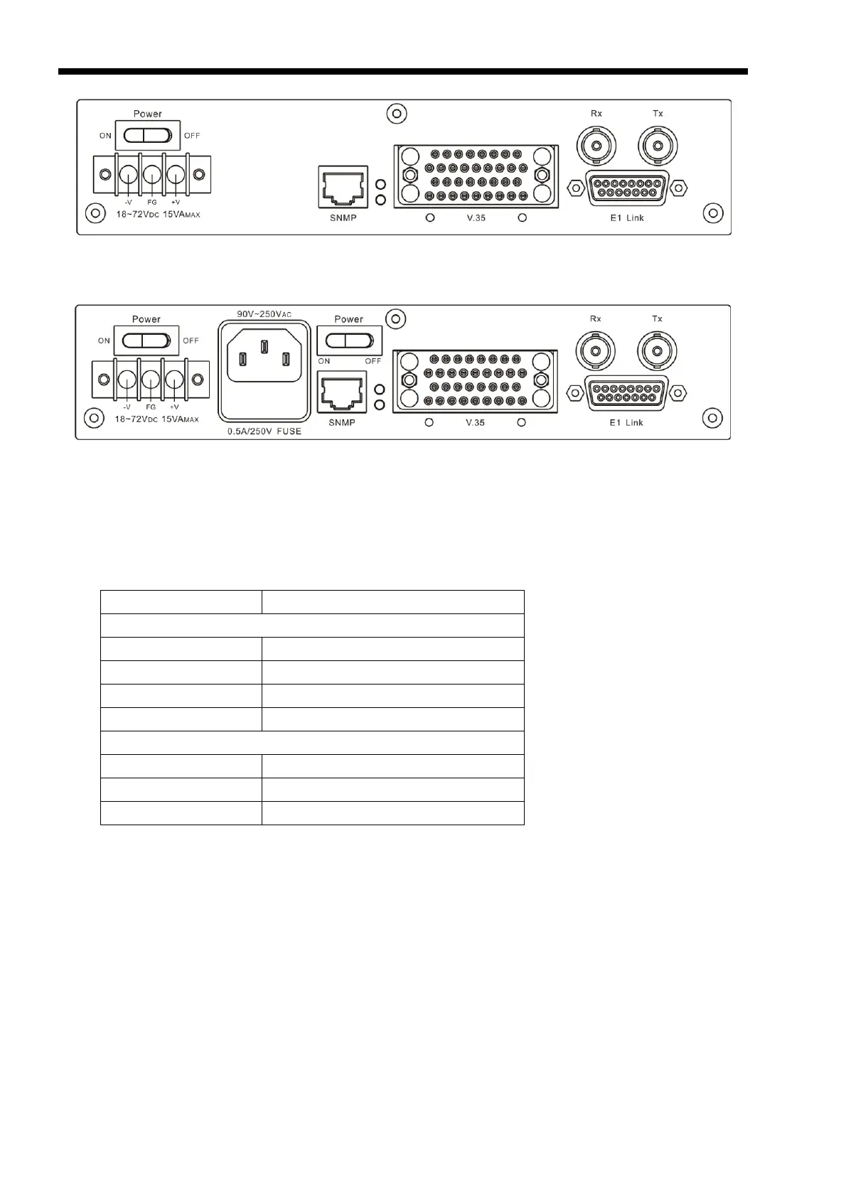
Figure 2-2 ETU-01A DC rear panel, Option: DCE (V.35)
Figure 2-3 ETU-01A AC+DC rear panel, Option: DCE (V.35)
2.5 E1 Line side
DB-15 Connector (balanced 120 Ohm)
The pin assignm
ent for DB-15 connector follows AT&T Pub 62411:
Pin: Function:
E1 Link
1 TTIP (Transmit data out)
9 TRING (Transmit data out)
3 RTIP (Receive data in)
11 RRING (Receive data in)
ALARM relay contact
7 common
8 NO (normally open)
15 NC (normally closed)
BNC coax connectors (unbalanced 75 Ohm)
Two BNC coax connectors marked RX and TX (Same function as the E1 line DB15 connector).
 Loading...