Appendix A. I/F Modules
79
May 2011
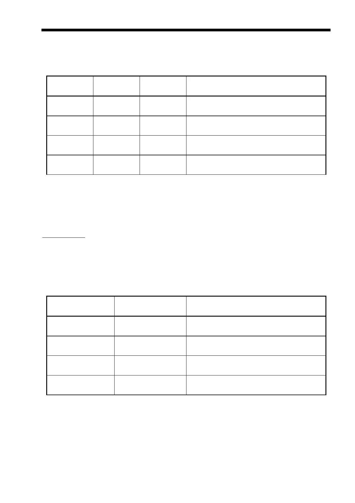
A.7 G.703/64K Co-directional Connector
When the ETU-01A is ordered with a G.703/64K interface, the physical interface is a 15-pin female
D-Sub type connector wired in accordance with Table A-8.
SIGNAL
FUNCTION
PIN DIRECTION DESCRIPTION
Protective
Ground
4
10
↔
Chassis ground.
May be isolated from Signal Ground.
Signal
Ground
8
↔
Common signal ground.
Transmitted
Data
3
11
To ETU-01A Serial Codirectional data from DTE.
Received
Data
1
9
Fm ETU-01A
Serial Codirectional data at the output of the
ETU-01A receiver.
Table A-8 G.703/64K Codirectional pin allocation
A.8 G.703/NRZ
When the ETU-01A is ordered with an NRZ interface, the physical interface is 4 BNC female
connectors wired in accordance with Table A-9.
Specifications:
Line Code: NRZ
Impedance: 50 ohms
Signal Level: Logic "1": 0V +/- 0.3V
Logic "0": -1.5V +/- 0.3V
Speed: 2048K Max.
SIGNAL
FUNCTION
DIRECTION DESCRIPTION
Received
Data
Fm ETU-01A
Serial NRZ data at the output of the ETU-01A
receiver.
Received
Timing
Fm ETU-01A
Serial NRZ timing at the output of the ETU-
01A receiver.
Transmitted
Data
To ETU-01A Serial NRZ data from DTE.
Transmit
Timing
To ETU-01A Serial NRZ timing from DTE.
Table A-9 NRZ/BNC pin allocation
Settings: (by adjustment of jumpers on interface card)
Rx timing; "Normal" or "Inverted"
Tx timing; "Normal" or "Inverted"
 Loading...