Chapter 3. LCD Operation
23
May 2011
Chapter 3. LCD Operation
3.1 General
This chapter describes the ETU-01A controls and indicators, and explains operation setup
procedures. Installation procedures (in Chapter 2) must be completed and checked before
attempting to operate the ETU-01A.
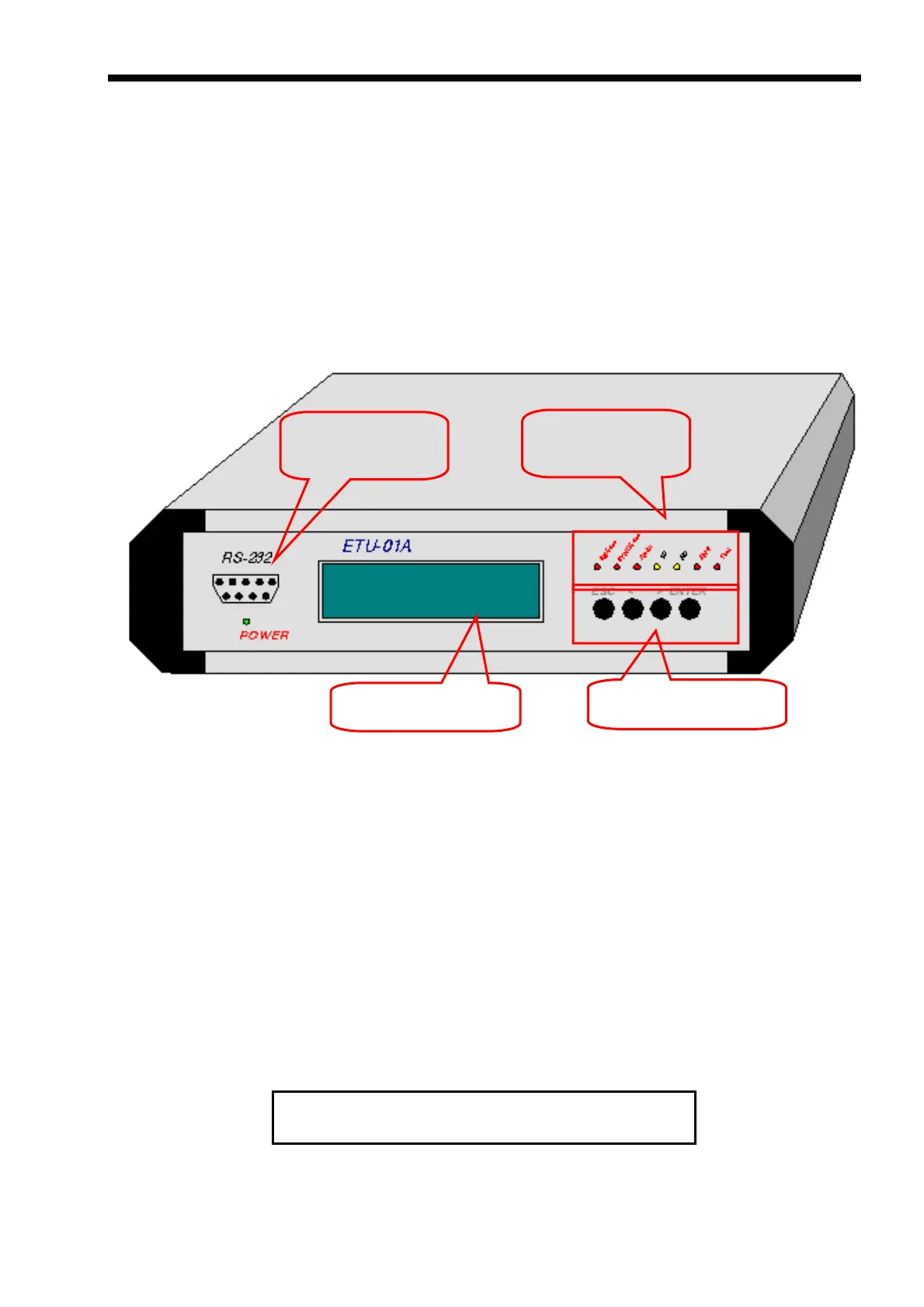
3.2 Controls and Indicators
All controls (push-button switches), LCD display and LED indicators are located on the ETU-
01A front panel. The momentary on pushbutton switches are used to activate menu selections and
select parameter settings.
Figure 3-1 : ETU-01A Front Panel
3.3 Operating Procedure
3.3.1 LCD and Menu Keys
The ETU-01A requires no operator attention once installed, except for occasional monitoring
of the front panel indicators. Intervention is only required when:
The ETU-01A has to be adapted to new operational requirements.
Diagnostic loops are required.
The ETU-01A is turned on when its AC power cord is connected to an AC power outlet and
the power switch is turned to the ON position. The ETU-01A will perform its internal POST (power
on self test) to verify CPU, RAM, ROM and FPGA integrity. The initial display looks like this:
E T U -01A / SNMP
S ELF TEST
Status LEDs
Menu Push-Buttons
16x2 LCD Display
RS-232 Console
 Loading...