Chapter 2. Installation
22
May 2011
2.7 DIP Switches and Jumper Settings
2.7.1 Caution
To avoid accidental electric shock, disconnect the ETU-01A power cord before opening the
cover. Access inside the equipment is only permitted to authorized and qualified service personnel.
2.7.2 Procedure
1. Turn power OFF, Disconnect the power cord from the AC mains.
2. Loosen the screws at the left/right of the rear panel.
3. Remove the PCB assembly, noting orientation for installation.
4. Adjust the DIP switches and jumpers as required, according to table 2-1.
5. Replace the PCB and tighten the screws.
Table 2-1
DIPSW1
Item Function Setting Factory Setting
1 E1 line impedance set 120 Ohm ALL OFF *
2 E1 line impedance set 75 Ohm ALL ON
This is the only internal DIP switch setting required for the ETU-01A. All other settings are
performed through LCD or Console user interface.
Chassis GND Jumper
Set this jumper to "CON" to connect logic ground to chassis. Set to "DIS" to separate logic and
chassis grounds. The default and normal position is disconnected.
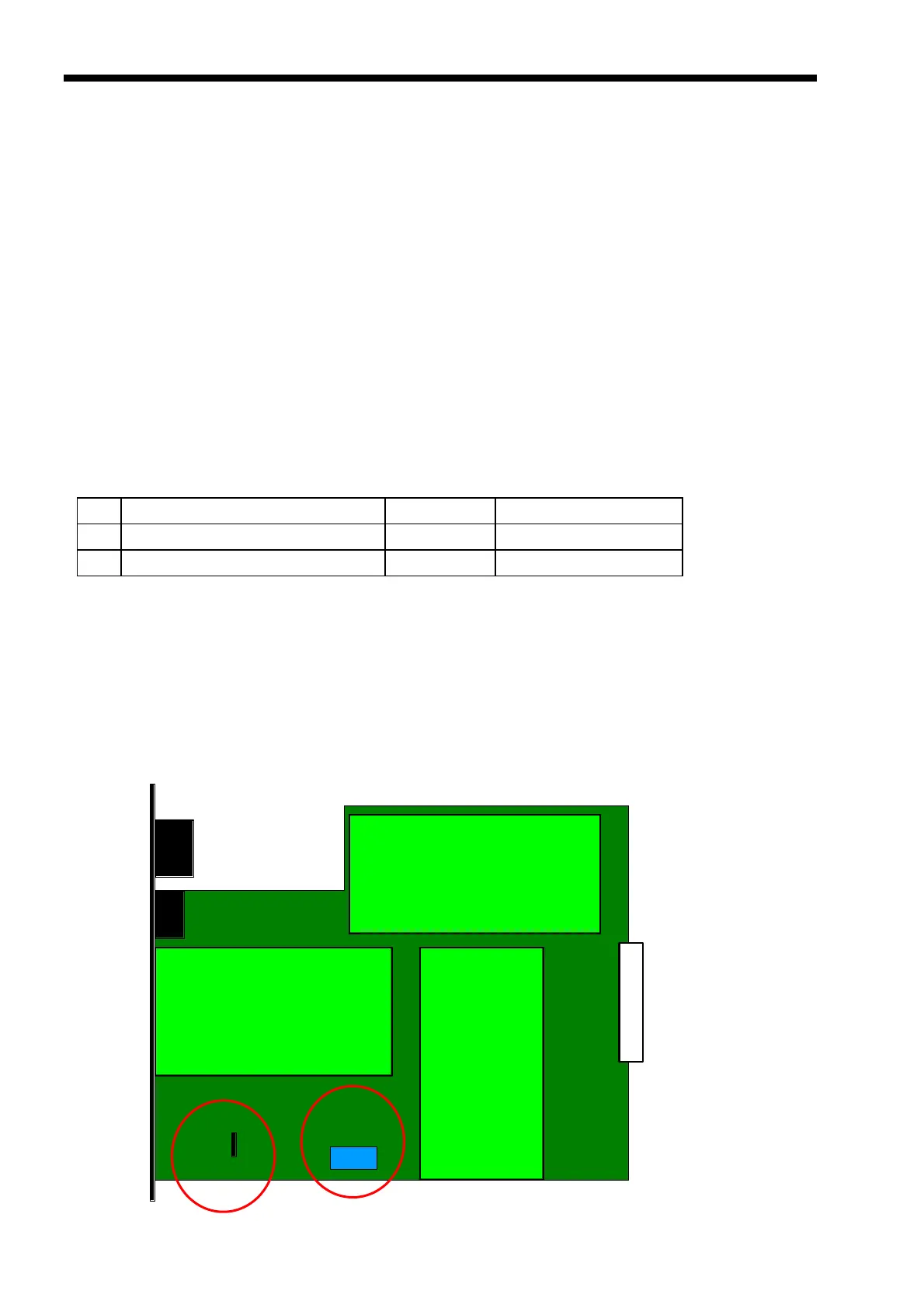
Please refer to the following figure for location of DIP switch and chassis jumper.
Figure 2-4 : ETU-01A Main PCB Assembly
DIPSW1
CON
SNMP
Option
DATA Port I/F
Card
Switching Power Supply
Connector
 Loading...