ELECTRICAL SYSTEM
140
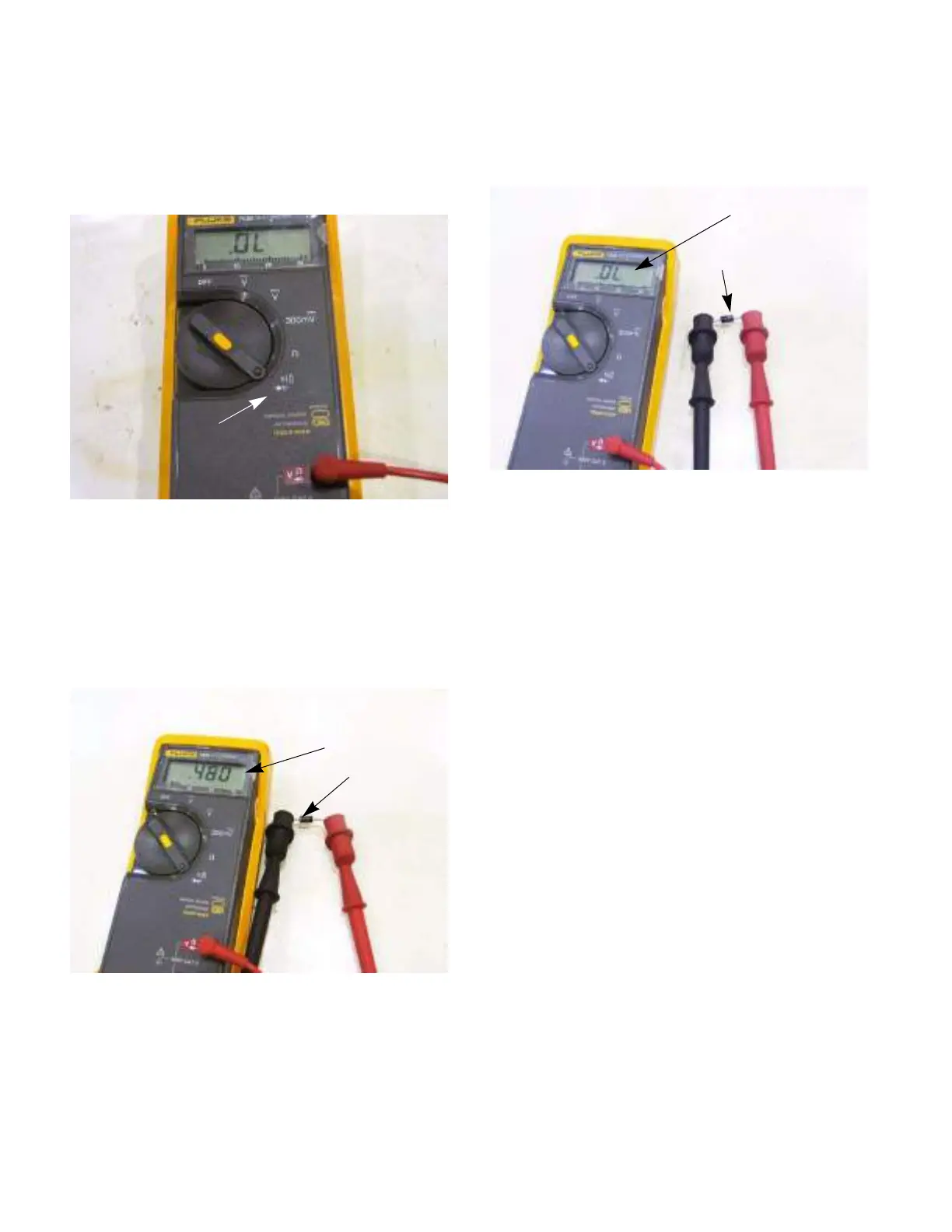
Testing a diode:
12a. Isolate the diode in the circuit.
12b. Set the DMM to the diode or Ω scale.
See Figure 7.47.
12c. Attach the negative lead of the DMM to the
side of the diode with a band on it.
12d. Place the positive lead on the other side of
the diode.
12e. There should be continuity.
See Figure 7.48.
12f. Switch the leads.
12g. The meter should indicate no continuity.
See Figure 7.49.
12h. If the results do not match the above,
replace the diode.
Figure 7.47
Diode scale
Figure 7.48
Continuity
Silver band
(-)
(+)
Figure 7.49
No continuity
Silver band
(-)
(+)

 Loading...