DRIVE SYSTEM-HYDROGEAR
25
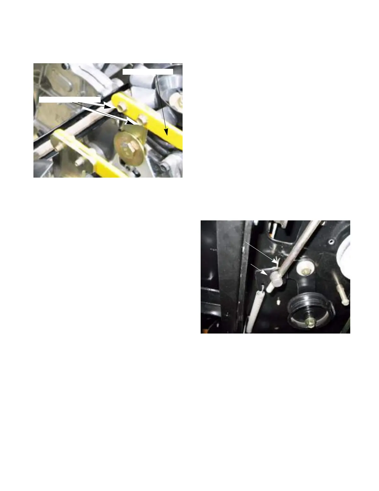
10. Remove the two screws that hold the transmis-
sion links to the shifter plate. See Figure 5A.6.
11. The belt can now be snaked out of the tractor.
12. Install the belt following the above steps in
reverse order.
NOTE: Tighten the electric PTO clutch bolt to a
torque of 450 - 600 in-lbs (51 - 68 Nm).
13. Test drive the tractor before returning to service.
Figure 5A.6
Transmission link
Remove these screws
Belt adjustment
The drive belt is tensioned by a spring loaded
moveable idler pulley. When the brakes are applied,
the drive belt is de-clutched. An adjustable linkage con-
nects the tensioner pulley to the brake shaft. A brake
link that is out of adjustment will prevent the moveable
idler from correctly tensioning and de-tensioning the
belt.
As the belt wears and stretches, the moveable idler
needs to push the belt in further to keep proper belt
tension. To do this, the ferrule at the end of the brake
link needs to be at the middle of the slot in the idler pul-
ley bracket. To adjust this brake link:
NOTE: The belt must be on when performing
this adjustment.
1. Release the parking brake.
2. Remove the deck as described in chapter 8 Cut-
ting Decks and Lift Shaft.
3. Remove the cotter pin and washer from the fer-
rule. See Figure 5A.7.
Figure 5A.7
Ferrule
Cotter pin

 Loading...