DRIVE SYSTEM-HYDROGEAR
28
Drive pedal shaft
To remove the drive pedal shaft:
1. Remove the deck as described in chapter 8 Cut-
ting Decks and Lift Shaft.
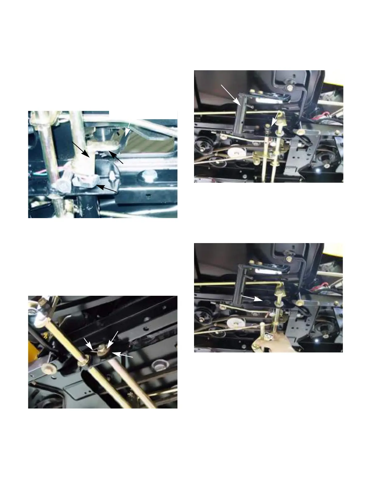
2. Disconnect the link between the steering gear-
box and the bell crank on the drive pedal shaft.
See Figure 5A.14.
NOTE: It does not matter which side of the link is
disconnected.
3. Disconnect the reverse switch.
4. Remove and discard the cotter pin on the left
side of the drive pedal shaft. See Figure 5A.15.
5. Remove the washer and hex bushing.
See Figure 5A.15.
6. Drive out the two roll pins that secure the drive
pedal bracket to the drive pedal shaft.
See Figure 5A.16.
7. Remove the hex bushing. See Figure 5A.16.
8. Slide the drive pedal shaft to the left to clear the
hole for the right side hex bushing.
See Figure 5A.17.
9. Install the drive pedal shaft by following the pre-
vious steps in reverse order.
10. Test drive the tractor before returning it to ser-
vice.
Figure 5A.14
Steering gearbox lever
Link
Bell
crank
Reverse switch
Figure 5A.15
cotter pin
Washer
Hex bushing
Figure 5A.16
Drive pedal bracket
Hex bushing
Figure 5A.17
Hole for hex bushing
 Loading...