CUTTING DECKS AND LIFT SHAFT
153
50" Deck ONLY
NOTE: The 50" deck roller assembly index
bracket has five adjustment holes.
A While supporting the roller assembly,
remove clevis pin and withdraw the clevis
pins from both of the roller index brackets.
See Figure 8.23.
B Position the roller assembly so that the
rollers are approximately 1/4" to 1/2"
above the flat surface below.
C Align the nearest index bracket holes with
the holes in the deck mounting brackets.
Insert the clevis pins through the deck
brackets and the index brackets and
secure with the click pins.
NOTE: The clevis pins should be in the corre-
sponding holes of both the left and right roller
index brackets.
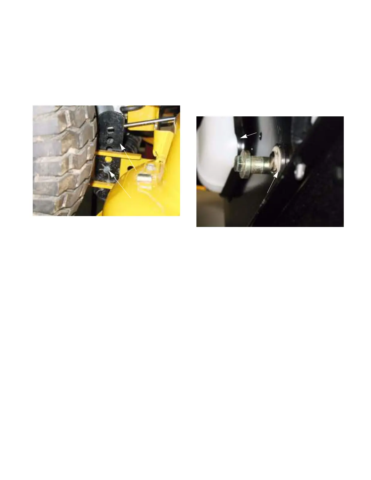
Figure 8.23
Index bracket
Clevis pin
Deck lift shaft assembly bushings
The deck lift shaft assembly bushings for the I-
series tractor can be replaced with out removing the
deck lift shaft assembly. To replace the bushings:
1. Remove the deck by following the steps
described at the beginning of this chapter.
2. Remove the E-ring that retains the lift shaft
bushing. See Figure 8.24.
3. Slide the old bushing out.
4. Slide the new bushing in.
5. Install the E-ring that retains the bushing.
6. Repeat steps 2 - 6 on the opposite side.
7. Install the deck.
8. Test drive the tractor in a safe area before
returning to service.
Figure 8.24
E-clip
Fuel tank
 Loading...