Communication Cable - Multiple Units
NOTE: Disregard this information and proceed to flow sensor schematic (optional) information when installing
single tank configurations.
Multiple units require a communication cable between each unit. Refer to the table below for the cable type, part
number and quantity required. Cables are attached to the RS485 terminal of the circuit board.
Table 2
System
Configuration
Cable Part Number Qty of Cables
required
“Kit” Part Number Qty of blocking
solenoids used.
Duplex Alternating 01016342 1 01016369 2
Duplex Parallel 01016327 1 N/A 0
Triplex Parallel 01016327 2 N/A 0
Duplex Progressive 01016327 1 01016333 2
Triplex Progressive 01016327 2 01016334 3
Multiple units can be set up as progressive flow, alternating or parallel operation. Refer to the instructions and
schematics below and on the following pages for connection to the circuit board.
Most multiple tank configurations will also require blocking valves (with the exception of the Hi-Flo 3e softener).
These are used to hold tanks offline until needed. Based on the chart above, you can determine how many
blocking solenoids are used. These solenoids are included in the alternating and progressive flow kits.
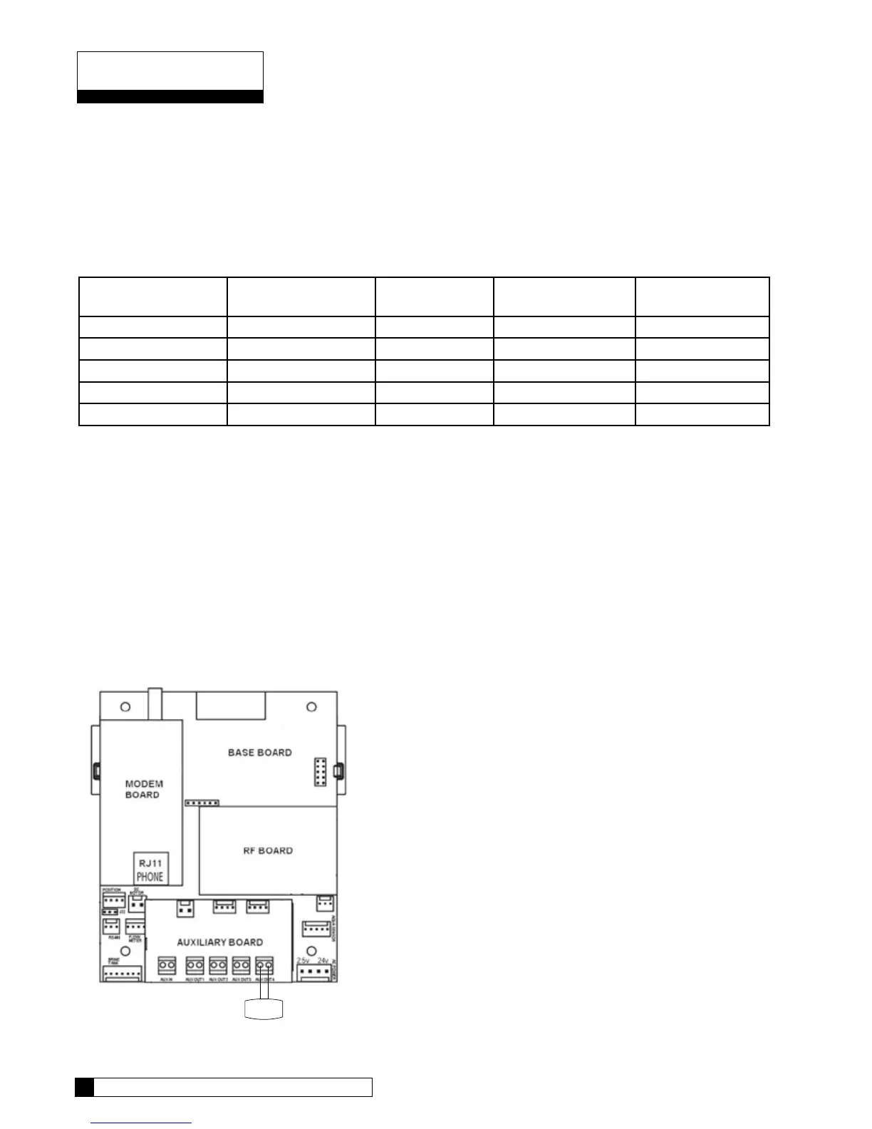
Blocking Solenoid Connection (used on Alternating and Progressive flow systems)
The solenoid valve wiring attaches to the Aux Out 4 output connection on the auxiliary circuit board. See
Figure 16 .
Schematic
Schematic 12
11 CULLIGAN GLOBAL ELECTRONIC CONTROLLER
Figure 16