(optional)
2535 & 2536
Signet
Black
Shield
Red
Black
Green
Red
Paddle Wheel
(optional)
Seametrics
Green
Red
Black
White
SINGLE OR PROGRESSIVE
Bare
Red
Green
Black
Red
Black
Wht/Clear
2" Autrol Turbine Meter
(optional)
Black
White
Red
2"Clack Meter
(optional)
Schematic 14
13 CULLIGAN GLOBAL ELECTRONIC CONTROLLER
Schematic
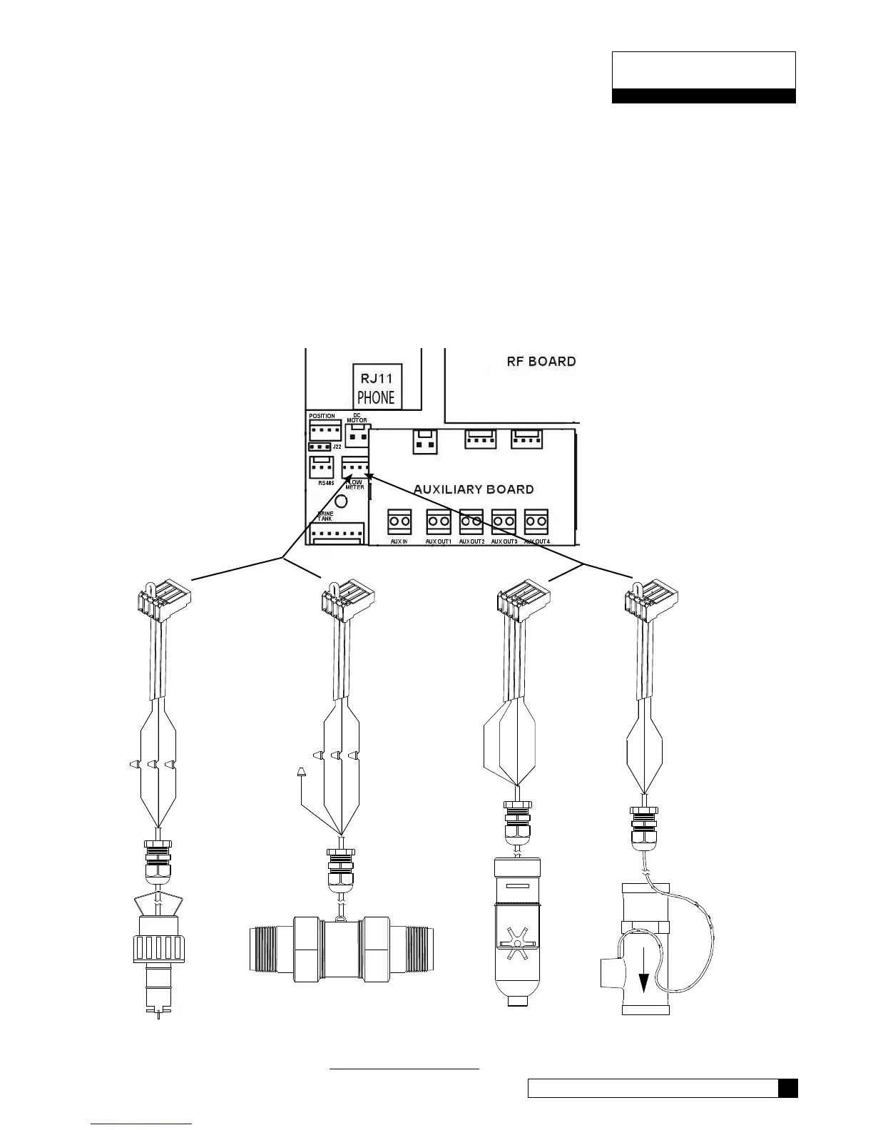
Flow Sensor Meter Connections (Optional)
The GBE Controller is capable of detecting the signal from a Hall effect sensor device to provide flow rate infor-
mation, totalization and volume based regeneration initiation.
There are several different types of flow measuring devices and differences in the wiring of the devices to the
GBE circuit board do exist. Refer to the drawings below.
For all but duplex alternating, a meter needs to be connected to each circuit board at the location shown below
in the drawing. For duplex alternating meter connection, please refer back to page 13, Duplex Alternating with
meter option.
SEE PAGE 41 FOR PROGRAMMING AND PAGE 63 FOR K FACTORS.
Figure 19
Connector
located at
end of meter
cable
Connector
01010255 included
with controller