Installation of Accessories
Installation of Accessories 34
33 CULLIGAN GLOBAL ELECTRONIC CONTROLLER
Installation of the Smart Brine Tank (SBT) Probe
After the Smart Brine Tank Probe is installed, it is necessary to configure some settings.
From the home screen, press the DOWN arrow to ACCESSORIES. Press the CHECK
MARK button.
Press the DOWN arrow key to scroll to SBT SENSOR. Press the CHECK MARK button at
SBT SENSOR.
Press the CHECK MARK button to change SBT SENSOR setting. Press the UP or DOWN
arrow to change from NOT INSTALLED to INSTALLED. Press the CHECK MARK when
the correct SBT SENSOR mode is displayed.
Press the CHECK MARK button to set BRINE TANK AREA setting. Press the UP or
DOWN arrow to change AREA SQ/IN. See chart below for correct BRINE TANK
AREA:
18 x 38 Brine Tank - 250 sq in 39 x 48 Brine Tank - 1190 sq in
24 x 40 Brine Tank - 450 sq in 42 x 48 Brine Tank - 1380 sq in
24 x 50 Brine Tank - 450 sq in
30 x 50 Brine Tank - 700 sq in
Press the CHECK MARK when the correct BRINE TANK AREA is displayed.
Press the CHECK MARK button to change SALT GEOMETRY setting. Press the UP or
DOWN arrow to change from PELLET, ROCK OR BRICK. Press the CHECK MARK
when the correct SALT GEOMETRY is displayed.
> 4) accessories
system ok
7:32 am 2-1-08
> 5) sbt sensor
sbt sensor
>installed
salt geometry
>pellet
brine tank area
>500 sq/in
Installing the Smart Brine Tank (SBT Probe) in to the Brine Tank
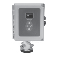
1. Place the smart brine probe on top of the brine plate as shown in Figure 24 .
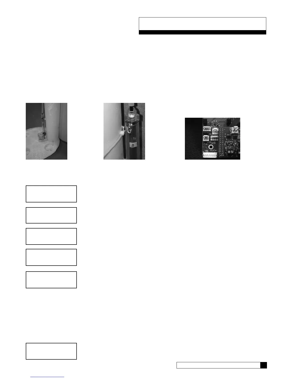
2. Loop the two zip ties thru the holes in the probe housing and loop the zip ties around the outside of the brine well as shown
in Figure 25. IMPORTANT! Tighten zip ties securely to prevent movement.
3. Use zip tie to snug the top of the brine tank probe against the top of the brine well.
4. Route the smart brine tank probe cable to an appropriate opening in the valve control housing. Use the strain-relief plug
provided with the SBT probe for installation.
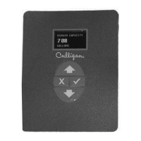
5. Plug the SBT probe connector into the circuit board at the position labeled “Brine Tank” - Figure 26.
Figure 24 Figure 25 Figure 26