Appendix C
Appendix B 66
65 CULLIGAN GLOBAL ELECTRONIC CONTROLLER
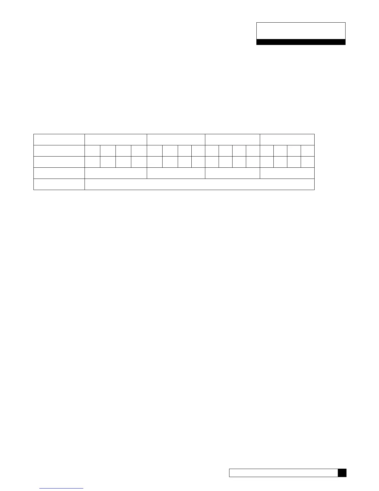
Each error bit is either ‘0’ meaning that this error is NOT present, or ‘1’ meaning that this error IS present. Each of
the four-bit sections (W, X, Y and Z) are then combined into a four digit binary word which is converted to a hexa-
decimal digit.
As an example, if there are no errors present, then the value would be 0x0000.
If there were a ‘Replace Media Filter’, ‘Aquasensor Salt Err’ and ‘Motor Position Sensor Error’ present then bits 4,
6 and 8 would be set to ‘1’ respectively and all other bits would be ‘0’.
W X Y Z
Error Bits
15 14 13 12 11 10 9 8 7 6 5 4 3 2 1 0
Binary
0 0 0 0 0 0 0 1 0 1 0 1 0 0 0 0
hexadecimal
0 1 5** 0
Error Flag
0x0150
*note that the first two characters of the error flag are always “0x” to signify that this is a hexadecimal number
** In hexadecimal, the number 4 bit equals 1, the number 5 bit equals 2, the number 6 bit equals 4, and the
number 7 bit equals 8. Therefore, when you add the #4 bit value to the #1 bit value, you get 5.
So the value of the error flag would be 0x0150 if these three errors were present.
NOTE: If the GBE is controlling a Filter (instead of a water softener) then the above message definitions are identi-
cal, but that error flags 1,2,3,6,9 and 11 will always be zero for a filter)
Progressive Flow System of Water Softeners controlled by GBE:
The format of the “status message” for a progressive flow network consists of a series of individual lines of informa-
tion, one line for each of the gbe controlled softeners. For example, in a triplex progressive flow network, every
10 minutes, the data port on the master unit will send out the following three lines of information:
CULL,A1,B1,C1,D1,E1,1
CULL,A2,B2,C2,D2,E2,2
CULL,A3,B3,C3,D3,E3,3
example: CULL,52754,3.7,1,9110,0x0000,1
CULL,42674,3.5,1,4321,0x0000,2
CULL,10204,0.0,4,5444,0x0000,3
The ‘1’ at the end of the first line indicates that this line is the status for the Master unit in the progressive flow net-
work. The ‘2’ and ‘3’ on the subsequent lines indicate that this data is for slave unit #1 and slave unit #2 respec-
tively. The information contained on each line is of the same format as described in the Single softener section
above.
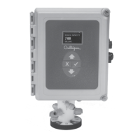
Electrical Connections
The Culligan Data Cable Connector is terminated with a D-sub9 style female termination. The customer must pro-
vide the following pin connections: