6
Curtis 1230 Manual, Rev. C
2 — INSTALLATION & WIRING: Controller
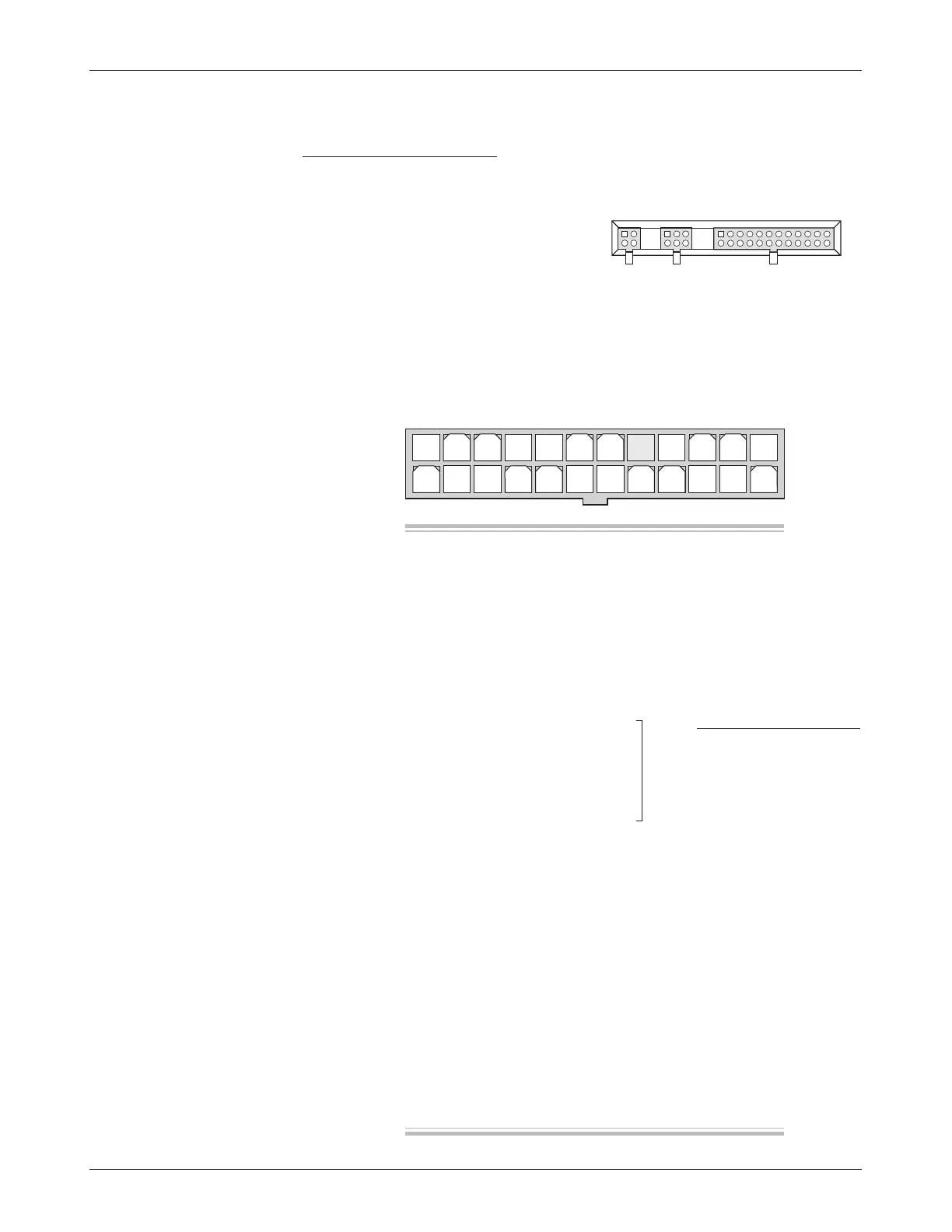
1 2 3 4 5 6 7 8 9 10 11 12
13 14 15 16 17 18 19 20 21 22 23 24
4-pin 6-pin 24-pin
J3 J2 J1
J1
CONNECTIONS
Low Current Connections
Three low current connectors (J1, J2, J3) are built into the 1230 controller.
They are located in a row on the top of the controller:
The 24-pin connector (J1) provides the logic control connections for the
contactor drivers and switches that are wired directly to the vehicle. The mating
connector is a 24-pin Molex Mini-Fit Jr. connector part number 39-01-2245
using type 5556 terminals.
WITH MULTIPLEXER
J1 Pin 1 keyswitch input (KSI)
J1 Pin 2 interlock
J1 Pin 3 mode switch input—M1 (open), M2 (closed)
J1 Pin 4 inhibit input
J1 Pin 5 pot high output
J1 Pin 6 wiper/0–5V input for throttle
J1 Pin 7 pot low input
J1 Pin 8 [not used]
J1 Pin 9 feed-through ground
J1 Pin 10 speed limit input
J1 Pin 11 feed-through input 1
J1 Pin 12 feed-through input 2
J1 Pin 13 forward switch input
J1 Pin 14 reverse switch input
J1 Pin 15 emergency reverse input
J1 Pin 16 emergency reverse check output
J1 Pin 17 Status LED output
J1 Pin 18 Battery LED output
J1 Pin 19 display power output
J1 Pin 20 display ground reference output
J1 Pin 21 display data output
J1 Pin 22 main contactor driver output
J1 Pin 23 auxiliary output 1
J1 Pin 24 auxiliary output 2
J1 Pin 9 mux supply
J1 Pin 10 mux data
J1 Pin 11 mux clock
J1 Pin 12 mux ground
NO MULTIPLEXER