15
Curtis 1230 Manual, Rev. C
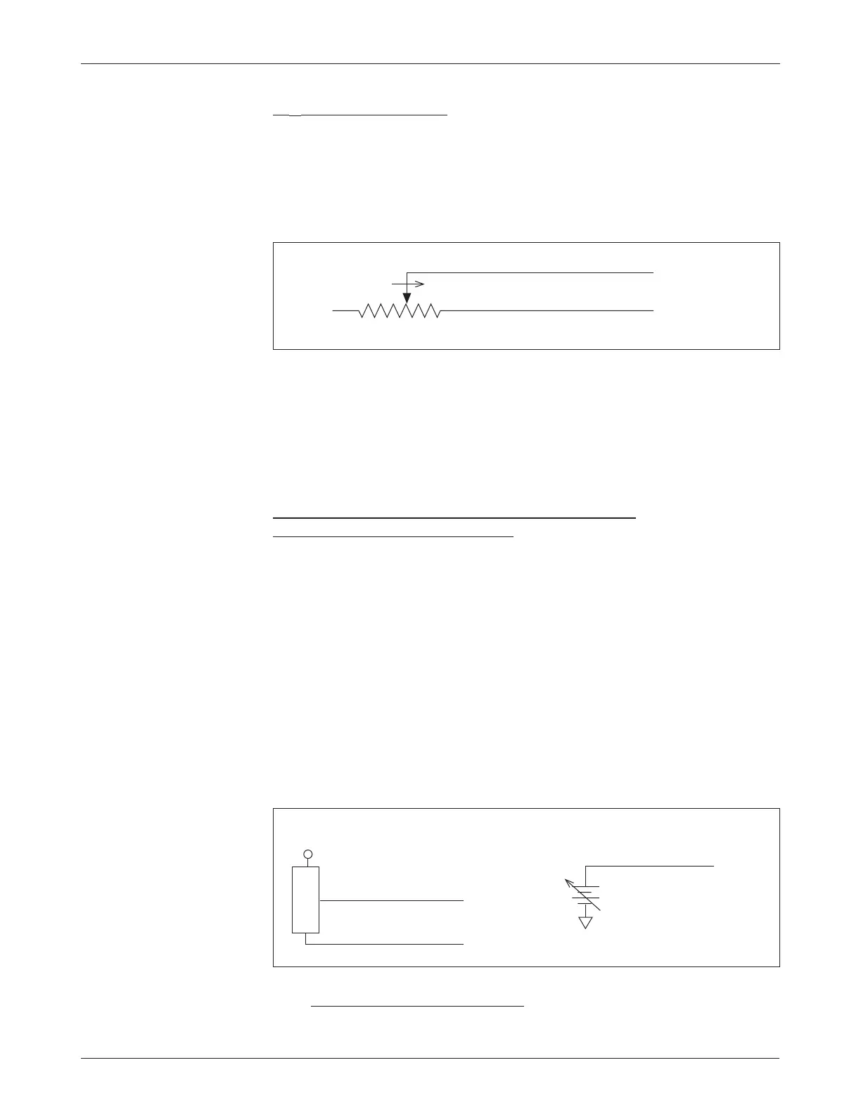
Fig. 6 Wiring for 5kΩ–0
throttle (“Type 1”).
2 — INSTALLATION & WIRING: Throttles
5kΩ–0 Throttle (“Type 1”)
The 5kΩ–0 throttle (called a “Type 1” throttle in the programming menu of
the 13XX programmer) is a 2-wire resistive throttle that connects between the
pot wiper pin (Pin 6) and the Pot Low pin (Pin 7), as shown in Figure 6. For
Type 1 devices, zero speed corresponds to a nominal 5 kΩ measured between
the pot wiper and Pot Low pins and full speed corresponds to 0
Ω.
Broken wire protection is provided by the controller sensing the current
flow from the wiper input (Pin 6) through the potentiometer and into the Pot
Low pin (Pin 7). If the Pot Low input current falls below 0.65 mA or its voltage
below 0.06 V, a throttle fault is generated and the throttle request is zeroed.
Note: The Pot Low pin must not be tied to ground (B-).
Single-Ended 0–5V Voltage Source, Current Source,
and 3-Wire Pot Throttles (“Type 2”)
With these throttles (“Type 2” in the programming menu) the controller looks
for a voltage signal at the wiper input. Zero speed corresponds to 0 V and full
speed to 5 V. A variety of devices can be used with this throttle input type,
including voltage sources, current sources, and 3-wire pots. The wiring for
each is slightly different and each has varying levels of throttle fault protection
associated with it.
0–5V Throttle
Two ways of wiring the 0–5V throttle are shown in Figure 7. The active range
for this throttle is from 0.2 V (at 0% Throttle Deadband) to 5.0 V (at 100%
Throttle Max), measured relative to B-. It is the responsibility of the OEM to
provide appropriate throttle fault detection for 0–5V throttles.
5kΩ–0
Pot Low input (Pin 7)
Wiper input (Pin 6)
FASTER
Fig. 7 Wiring for 0–5V
throttles (“Type 2”).
Sensor-referenced 0–5V source
+
-
B-
+
SENSOR GROUND
SENSOR OUTPUT (0–5V)
S E N S O R
Pot Low input (Pin 7)
0–5V input
(Pin 6)
0–5V input (Pin 6)
Ground-referenced 0–5V source
Sensor-referenced 0–5V throttles must provide a Pot Low current greater
than 0.65 mA to prevent shutdown due to pot faults. It is recommended that