17
Curtis 1230 Manual, Rev. C
2 — INSTALLATION & WIRING: Throttles
0–5kΩ Throttle (“Type 3”)
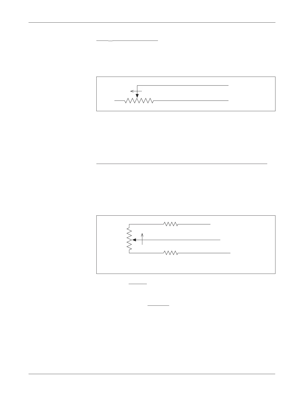
The 0–5kΩ throttle (“Type 3” in the programming menu) is a 2-wire resistive
throttle that connects between the pot wiper pin and the Pot Low pin, as shown
in Figure 10. Zero speed corresponds to 0
Ω measured between the two pins
and full speed corresponds to 5 k
Ω.
Broken wire protection is provided by the controller sensing the current
flow from the wiper input through the potentiometer and into the Pot Low
pin. If the Pot Low input current falls below 0.65 mA or its voltage below 0.06
V, a throttle fault is generated and the throttle request is zeroed. Note: The Pot
Low pin must not be tied to ground (B-).
Wigwag-Style 0–5V Voltage Source and 3-Wire Pot Throttle (“Type 4”)
These throttles (“Type 4” in the programming menu) operate in true wigwag
style. No signals to the controller’s forward and reverse (or lift and lower) inputs
are required; the action is determined by the wiper input value. The interface to
the controller for Type 4 devices is similar to that for Type 2 devices; see Figure
11 for wiring a wigwag 3-wire pot. The neutral point for Type 4 throttles is
with the wiper at 2.5 V, measured between Pot Low (Pin 6) and B-.
Fig. 10 Wiring for 0–5kΩ
throttle (“Type 3”).
0–5kΩ
Pot Low input (Pin 7)
Wiper input (Pin 6)
FASTER
For the traction throttle, the controller will provide increasing forward
speed as its wiper input value (Pin 4) is increased above the neutral point,
and increasing reverse speed as the wiper input value is decreased below the
neutral point. For the hydraulic throttle, the controller will provide increasing
Lift speed as its wiper input value (Pin 21) is increased above neutral, and in
-
creasing Lower speed as the wiper input value is decreased below neutral. The
minimum and maximum wiper voltage for either throttle must not exceed the
0.5V and 4.5V fault limits.
When a 3-wire pot is used and the Pot Low Check parameter (see Section 3,
page 28) is set to On, the controller provides full fault protection for Type 4
traction throttles. Any potentiometer value between 1 k
Ω and 10 kΩ is sup-
ported. When a voltage throttle is used, it is the responsibility of the OEM
Fig. 11 Wiring for wigwag
3-wire potentiometer throttle
(“Type 4”).
1kΩ–10kΩ
Wiper input (Pin 6)
Pot Low input (Pin 7)
Pot High output (Pin 5)
FASTER
*
*
* Series resistor required unless throttle pot
voltage range restricted to 0.5–4.5 V
(i.e., a value approx. 12% of throttle pot).