12
Curtis 1230 Manual, Rev. C
2 — INSTALLATION & WIRING: Controller
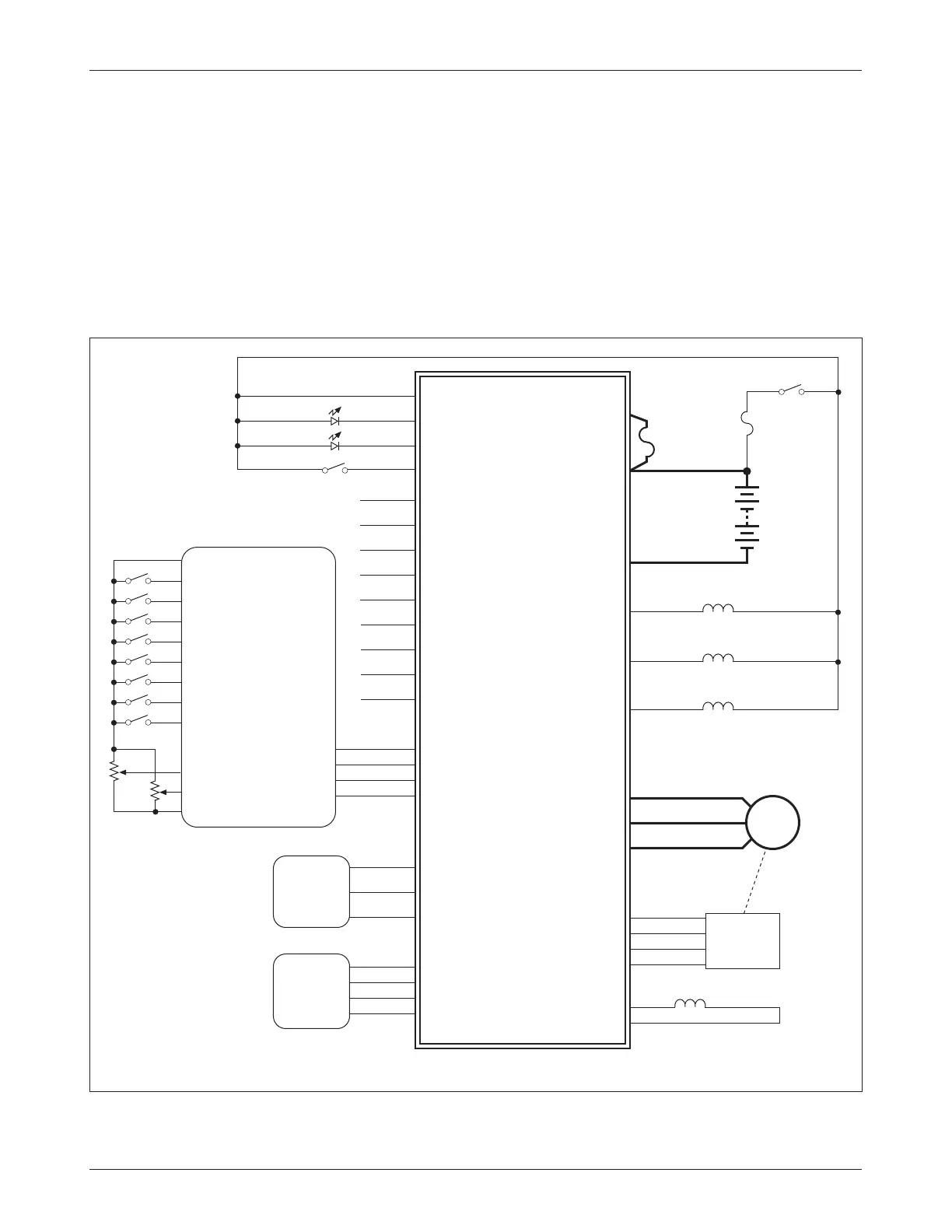
Fig. 5 Standard wiring configuration C: Curtis 1230-2X01 controller, in applications
with a 1312 tiller multiplexer and a proportional valve on the hydraulic line.
WIRING: Standard Configuration C (with multiplexer & PV)
Figure 5 shows the typical wiring configuration for applications where a pro
-
portional valve is used with the tiller multiplexer. Most 1230 models designed
for use with a multiplexer include an internal main contactor (see specifications
in Table C-1); for the 1230-2301 and -2401 models, which do not, the main
contactor should be wired as shown in Figure 3. If there is a load hold valve,
it needs to be controlled externally.
The proportional valve in configuration C is controlled by the hydraulic
throttle in the multiplexer, providing variable speed lift/lower operation.
F+
B-
U
V
W
Enc Supply
Enc A
Enc B
Enc Ground
PV
PV Retur
n
Auxiliary Output 1
Auxiliary Output 2
B+
Load Hold Valve
1230-2X01 CONTROLLER
Pot Low
J1-7
Emerg Rev Check
J1-16
Emergency Reverse
J1-15
Mode (M1/M2)
J1-3
Reverse
J1-14
Interlock
J1-2
Battery LED
Battery LED
Status LED
KSI
J1-1
Prog Supply
J3-4
Prog Receive
J3-1
Prog Transmit
J3-3
Prog Ground
J3-2
AC
MOTOR
SPEED
ENCODER
J2-1
J2-2
J2-4
J2-5
J2-6
J2-3
Proportional
Valve
J1-23
Keyswitch
BA
TTERY
Status LED
Interlock
Inhibit
J1-17
Pot High
J1-18
Throttle Wiper
J1-6
Disp Supply
J1-19
Disp Data
J1-21
Disp Ground
J1-20
CURTIS
840
DISPLAY
(Spyglass)
CURTIS
1311/1314
PROGRAMMER
J1-24
Lift Relay
J1-22
Load Hold Valve
E-M Brake
Po
wer
Fuse
(mounted
on controller)
Control
Fuse
Forward
J1-13
J1-5
J1-4
Mux Supply
J1-9
Mux Data
J1-10
Mux Clock
J1-11
Mux Ground
J1-12
5
6
8
J3-6
J3-3
J3-4
J3-2
Switch and throttle inputs can be connected
to either the controller or the multiplexer, or
to both as an “or” function.
Inhibit
Emergency Reverse
Mode (M1/M2)
Reverse
Lift
Lower
Forward
+5V
Ground
Throttle
Hydraulic Throttle
CURTIS
1312
TILLER
MULTIPLEXER
See page 20 for
multiplexer pinout.
Speed Limit