20
Curtis 1230 Manual, Rev. C
2 — INSTALLATION & WIRING: Tiller Multiplexer & Switches, etc.
WIRING: Tiller Multiplexer
The Curtis 1312 Multiplexer provides monitoring and control capability for
up to 12 analog or digital signals from operator controls on the tiller. Each
signal is sampled every 20 milliseconds for fast response.
The mating 6-pin connector is Molex 39-01-2065 and the mating 24-pin
connector is Molex 39-01-2245, both with 39-00-0039 (18–24 AWG) pins.
CONTACTOR, SWITCHES, and OTHER HARDWARE
Speed Encoder
A quadrature speed encoder for rotor speed measurement is required to ensure
precise speed control of the AC motor. The controller provides power supply
and ground reference lines as well as A and B signal inputs with internal pull-up
resistors. Encoder resolution can range from 2 to 200 pulses per revolution.
The encoder inputs are designed to work with open-collector output
quadrature encoders such as SKF sensorized bearings. If you intend to use a
different type of encoder or sensors please contact your local Curtis office.
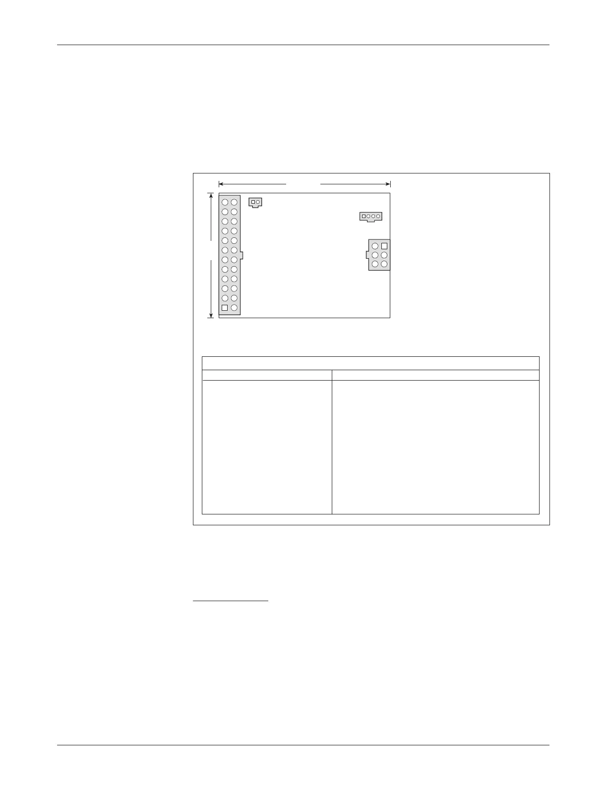
Fig. 13 Wiring guide and
mounting dimensions for
Curtis 1312 Multiplexer.
The 1312 provides four connectors:
J1 is a connector that can be used
to inhibit the controller during
battery charging.
J2 is not used.
J3 is the connector to the controller.
J4 is the connector for all other I/O.
WIRING GUIDE
PIN # FUNCTION
J1-1 N.C.
-2 Inhibit
J3-1 N.C.
2 1230 pin J1-12 (mux ground)
3 1230 pin J1-10 (mux data)
4 1230 pin J1-11 (mux clock)
5 N.C.
6 1230 pin J1-9 (mux supply)
CURTIS 1312
MULTIPLEXER
J1
J2
J3
J4
PIN # FUNCTION
J4-1 N.C.
-2 Mode switch
(M1/M2)
-3 Hydraulic throttle
-4 +5V
-5 N.C.
-6 N.C.
-7 N.C.
-8 N.C.
-9 N.C.
-10 N.C.
-11 +5V
-12 Reverse switch
PIN # FUNCTION
J4-13 +5V
-14 +5V
-15 Ground
-16 Speed limit
-17
Lower switch
-18 Lift switch
-19 Horn
-20 Emerg. rev. switch
-21 Traction throttle
-22 Ground
-23 +5V
-24 Forward switch
76 (3.0)
56
(2.2)
Dimensions in millimeters (and inches)