19
Curtis 1230 Manual, Rev. C
2 — INSTALLATION & WIRING: Emerg. Rev. Check & Spyglass Display
automatically driven in the reverse direction at the programmed emergency
reverse acceleration rate and speed until the emergency reverse switch is released
or the emergency reverse time limit is reached.
CAUTION: The sequence of the motor phase connections will affect the
operation of the emergency reverse feature. The forward and reverse switches
and the
U, V, W connections must be configured so that the vehicle drives away
from the operator when the emergency reverse button is pressed.
WIRING: Emergency Reverse Check
A wire connected directly to the emergency reverse switch provides for broken
wire detection when that feature is programmed On (see Section 3, page 33).
The emergency reverse check output wire periodically pulses the emergency
reverse circuit to check for continuity in the wiring. If there is no continuity,
the controller output is inhibited until the wiring fault is corrected.
If the option is selected and the check wire is not connected, the vehicle
will not operate. If the option is not selected and the check wire is connected,
no harm will occur—but continuity will not be checked.
Emergency reverse checking is disabled if the emergency reverse input
is configured to accept normally closed switches.
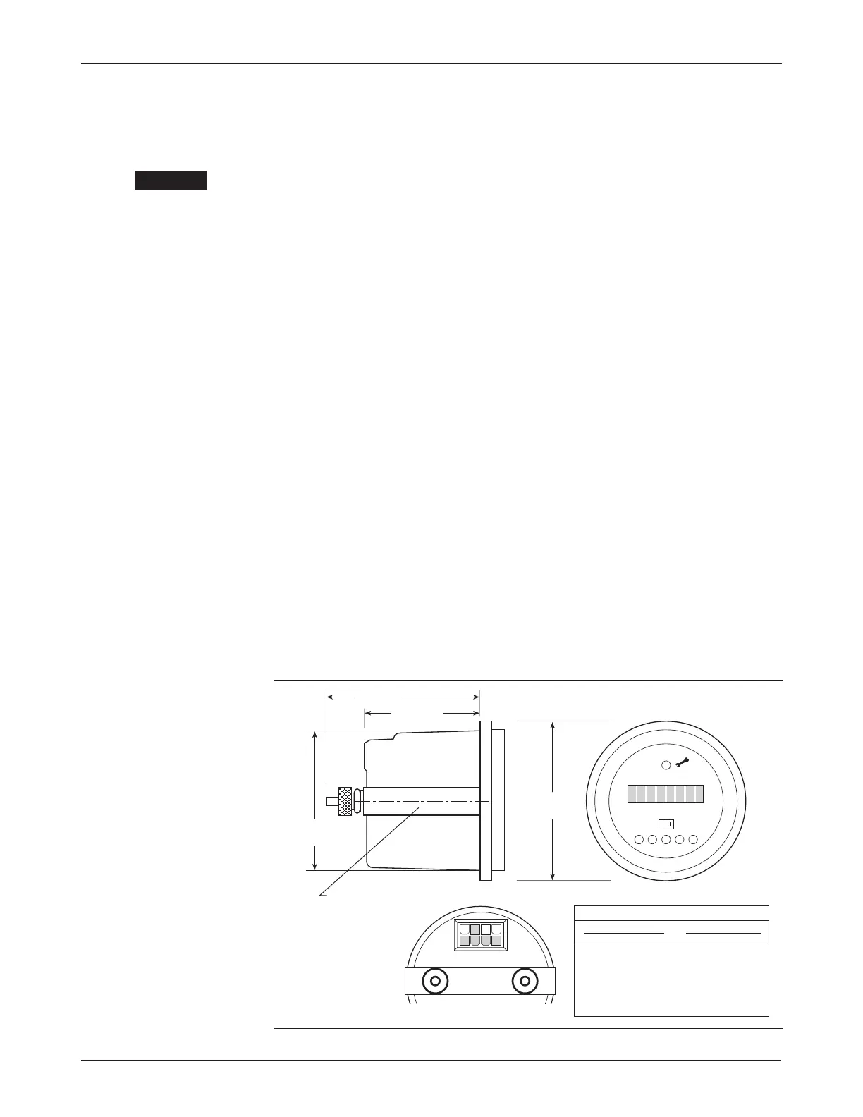
WIRING: Spyglass Display
The Curtis 840 Spyglass features an 8-character LCD display that sequences
between hourmeter, BDI, and fault messages. Depending on the model, either
three or six indicator LEDs are also located on the face of the gauge. The mating
8-pin connector is Molex 39-01-2085, with 39-00-0039 (18–24 AWG) pins.
Fig. 12 Wiring guide and
mounting dimensions for
Curtis 840 Spyglass display.
840 SPYGLASS 1230 CONTROLLER
PIN # FUNCTION J1 PIN #
1–4 N.C. –
5 power supply
19
6 receive data 21
7 N.C. –
8 ground (B+)
20
58
(2.25)
44 (1.75)
58 (2.25)
52
(2.0)
“U” clamp for
up to 6 (0.25)
panel thickness
WIRING GUIDE
0 1
8 5
4 1
☞
C A U T I O N
Dimensions in millimeters (and inches)