9
Curtis 1230 Manual, Rev. C
2 — INSTALLATION & WIRING: Controller
☞
C A U T I O N
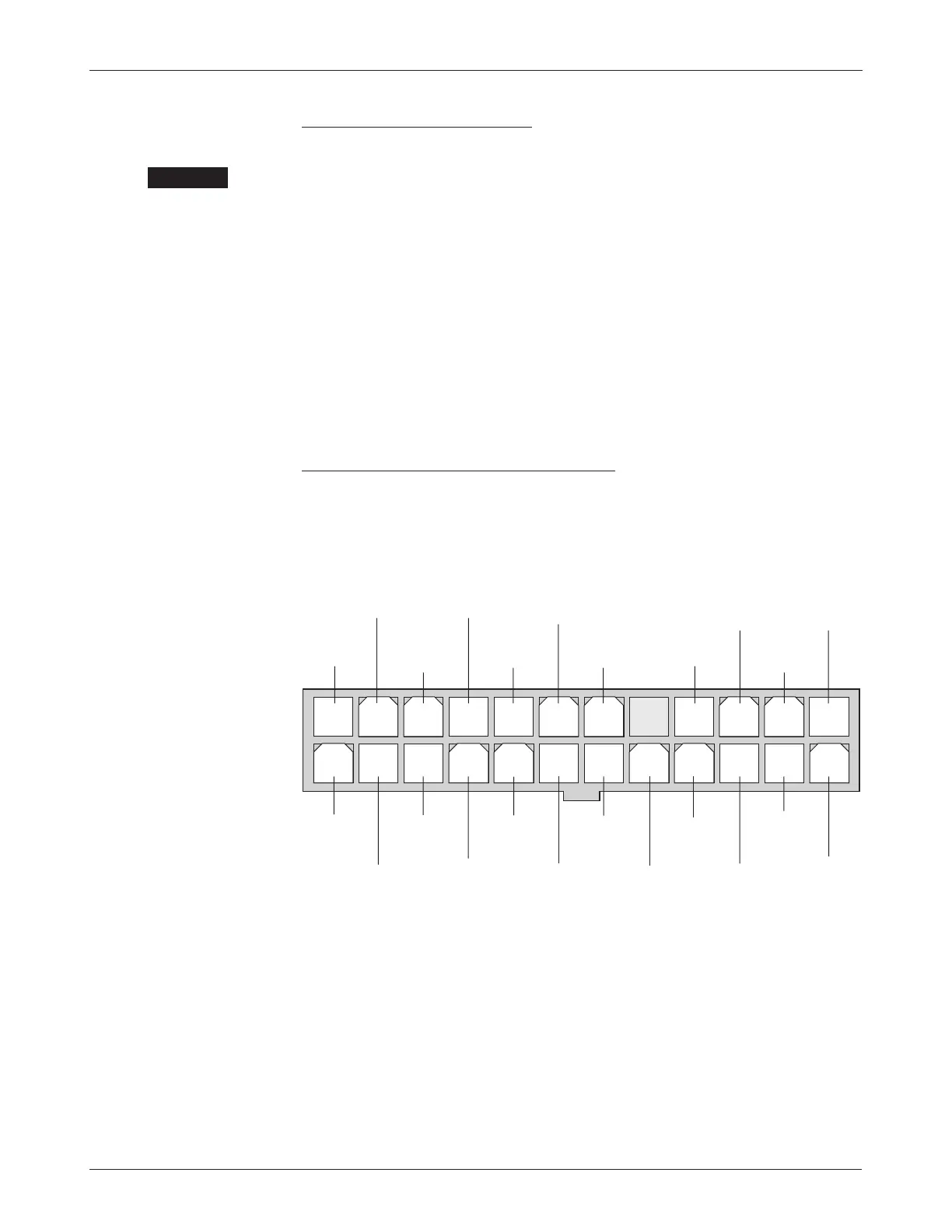
13 14 15 16 17 18 19 20 21 22 23 24
1 2 3 4 5 6 7 8 9 10 11 12
LIFT
RELA
Y
(feed-thru)
DISPLAY
SUPPLY
DISPLAY
GROUND
FORWARD
SWITCH
24-pin detail (see Fig. 3):
BATTERY
LED
POT
LOW
SPEED
LIMIT
PO
T
INHIBIT
LOWERING
VALV
E
(feed-thru)
EMERGENCY
REVERSE
EMERGENCY
REVERSE
CHECK
POT
HIGH
AU
X
GROUND
DISPLAY
DATA
REVERSE
SWITCH
LOWER
SWITCH
(feed-thru)
INTERLOCK
MODE
SWITCH
(M1/M2)
KEYSWITCH
INPUT (KSI)
THROTTLE
WIPER
MAIN
CONTACTO
R
LIFT
SWITCH
(feed-thru)
STATUS
LED
Power Wiring, Configuration A
Motor phase wiring is straightforward, with the motor’s U, V, W phases con-
nected directly to the controller’s
U, V, W studs. CAUTION: The sequence of the
motor phase connections will affect the operation of the emergency reverse
feature. The forward and reverse switches and the
U, V, W connections must
be configured so that the vehicle drives away from the operator when the
emergency reverse button is pressed.
The negative battery terminal is always connected directly to the B- stud.
The positive battery terminal is typically connected to the
F+ stud via the ex-
ternal main contactor, as shown in Figure 3. If the main fuse in not mounted
on the controller,
F+ is not used and the positive battery terminal is connected
to the
B+ stud.
If a main contactor is not required, the positive battery terminal can be
connected directly to the
B+ or F+ stud on the controller.
Standard Control Wiring, Configuration A
Wiring for the input switches and contactors is shown in Figure 3; the 24-pin
connector is shown in more detail below.
The main contactor coil must be wired directly to the controller as shown in
Figure 3. The controller can be programmed to check for welded or missing
contactor faults and uses the main contactor coil driver output to remove power
from the controller and motors in the event of various other faults. If the main
contactor coil is not wired to J1 Pin 22, the controller will not be able to
open the main contactor in serious fault conditions and the controller will
not be protected against reverse battery polarity.
Feed-throughs from J1 Pin 11 to Pin 23 and from J1 Pin 12 to Pin 24
are provided as a convenience, to simplify the wiring harness for lift/lower.