16
Curtis 1230 Manual, Rev. C
2 — INSTALLATION & WIRING: Throttles
the maximum Pot Low current be limited to 55 mA to prevent damage to the
Pot Low circuitry.
Ground-referenced 0–5V throttles require setting the Pot Low Check
parameter (see Section 3, page 28) to Off; otherwise the controller will register
a throttle fault. For ground-referenced 0–5V throttles, the controller will detect
open breaks in the wiper input but cannot provide full throttle fault protection.
Also, the controller recognizes the voltage between the wiper input and
B- as the applied throttle voltage and not the voltage from the voltage source
relative to the Pot Low input.
For either throttle input, if the 0–5V throttle input (Pin 6) exceeds 5.5 V
relative to B-, the controller will register a fault and shut down.
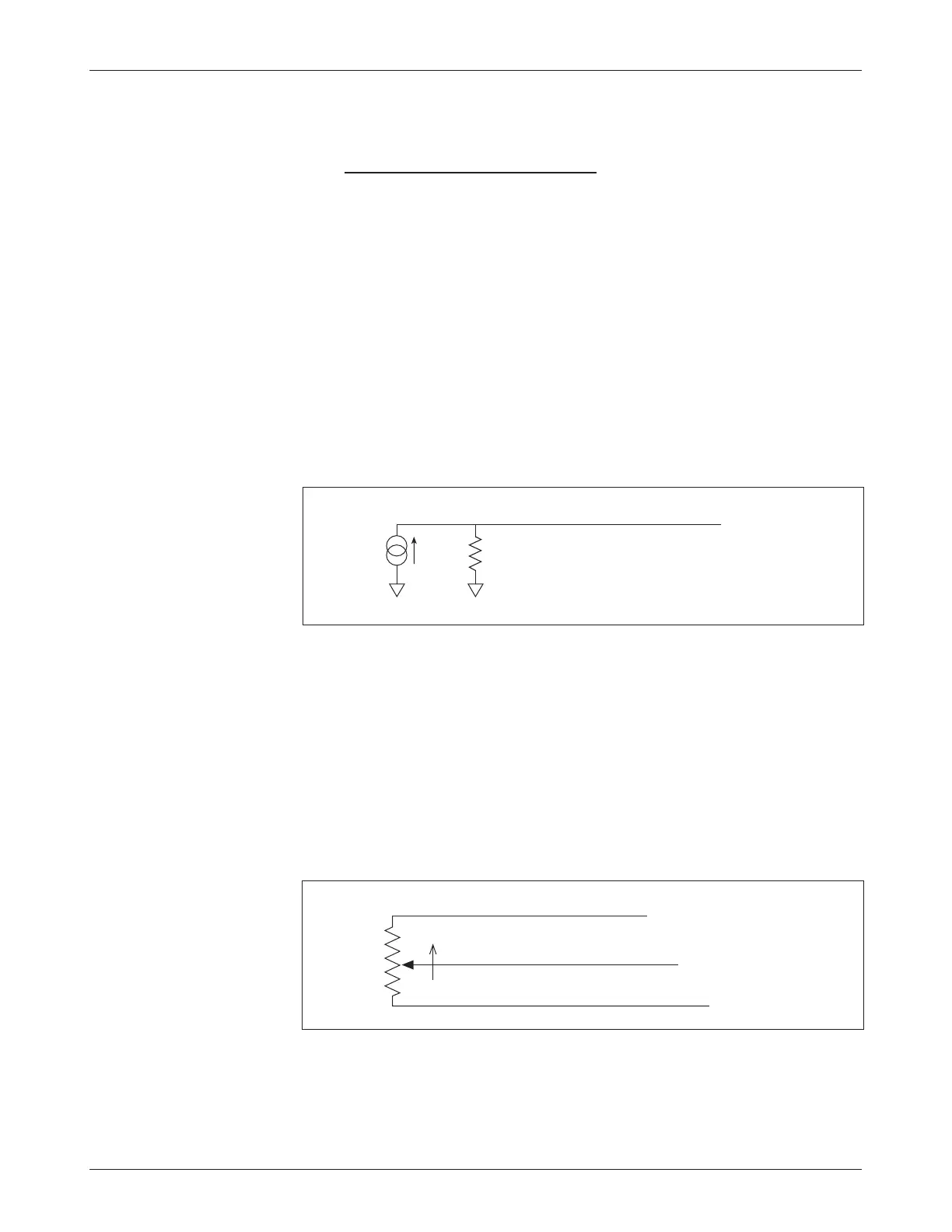
Current Source Used As a Speed Control Device
A current source can be used as a throttle input as shown in Figure 8. A resistor,
R
throttle
, must be used to convert the current source value to a voltage. The resistor
should be sized to provide a 0–5V signal variation over the full current range.
Fig. 8 Wiring for current
source throttle (“Type 2”).
R
throttle
I
source
B-B-
0–5V input (Pin 6)
It is the responsibility of the OEM to provide appropriate throttle fault
detection for current sources used as throttles.
3-Wire Pot Throttle (1–10 kΩ)
The 3-wire potentiometer is used in its voltage divider mode, with the voltage
source and return being provided by the 1230 controller. Pot High provides a
current limited 5 V source to the pot, and Pot Low provides the return path.
Wiring is shown in Figure 9 and also in the three standard wiring diagrams,
Figures 3, 4, and 5. Potentiometers with total resistance values between 1 k
Ω
and 10 k
Ω can be used.
Fig. 9 Wiring for 3-wire
potentiometer throttle
(“Type 2”).
1kΩ–10kΩ
Wiper input (Pin 6)
Pot Low input (Pin 7)
Pot High output (Pin 5)
FASTER
When a 3-wire pot is used and the Pot Low Check parameter (see Sec-
tion 3, page 28) is set to On, the controller provides full fault protection in
accordance with EEC requirements.