13
Curtis 1230 Manual, Rev. C
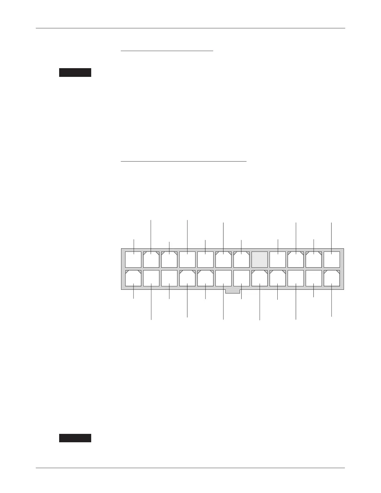
13 14 15 16 17 18 19 20 21 22 23 24
1 2 3 4 5 6 7 8 9
10 11 12
LIFT
RELA
Y
(AUX OUTPUT 1)
DISPLAY
SUPPLY
DISPLAY
GROUND
FORWARD
SWITCH
24-pin detail (see Fig. 5):
BATTERY
LED
POT
LOW
MUX
DATA
INHIBIT
E-M
BRAKE
(AUX OUTPUT 2)
EMERGENCY
REVERSE
EMERGENCY
REVERSE
CHECK
POT
HIGH
MUX
SUPPL
Y
DISPLA
Y
DATA
REVERSE
SWITCH
MUX
GROUND
INTERLOCK
MODE
SWITCH
(M1/M2)
KEYSWITCH
INPUT (KSI)
THROTTLE
WIPER
LOAD
HOLD
VALVE
*
STATUS
LED
MUX
CLOCK
*
Main contactor output for 1230-2301 and -2401;
no Load Hold available for these models.
☞
C A U T I O N
2 — INSTALLATION & WIRING: Controller
Power Wiring, Configuration C
Motor phase wiring is straightforward, with the motor’s U, V, W phases con-
nected directly to the controller’s
U, V, W studs. CAUTION: The sequence of the
motor phase connections will affect the operation of the emergency reverse
feature. The forward and reverse switches and the
U, V, W connections must
be configured so that the vehicle drives away from the operator when the
emergency reverse button is pressed.
The negative battery terminal is always connected directly to the B- stud.
The positive battery terminal is typically connected to the
F+ stud, as shown
in Figure 5. If the main fuse in not mounted on the controller,
F+ is not used
and the positive battery terminal is connected to the
B+ stud.
Standard Control Wiring, Configuration C
Wiring for the input switches and contactors is shown in Figure 5; the 24-pin
connector is shown in more detail below.
The controller can be programmed to check for welded or missing contactor
faults and uses the internal main contactor to remove power from the controller
and motor in the event of various faults, including reversed battery polarity.
The controller must be configured to control the proportional valve volt
-
age by programming the Auxiliary Output Type parameter to 4, which assigns
the PWM capability of J2 Pin 6 to the PV and the digital on/off output J1
Pin 24 to the electromagnetic brake. As the brake is no longer connected to J2
Pin 6 the Brake Fault Check parameter is moot and brake fault checking is
disabled. The Brake Holding Voltage parameter is also moot, and the holding
voltage is set at 100%.
☞
C A U T I O N