6
Curtis 1212 Manual
2 — INSTALLATION & WIRING
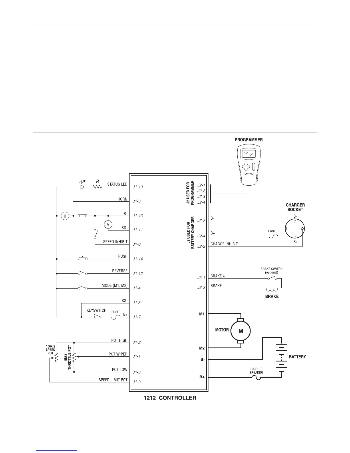
Fig. 3 Standard wiring configuration, Curtis 1212 controller.
WIRING: STANDARD INSTALLATION
The wiring diagram presented in Figure 3 shows a typical installation. This
installation is shown with a single-ended 3-wire 5kΩ potentiometer throttle
and a reverse switch. With wigwag throttles, a reverse switch is not used and
Pin 12 is left unconnected.
The optional speed inhibit input can be wired into the circuit in various
ways; in the standard installation shown here, it is B- active (Speed Inhibit
parameter set to 0).
The J2 connector can be used interchangeably for the programmer or
for the battery charger.