Curtis 1212 Manual
7
2 — INSTALLATION & WIRING: Throttle
THROTTLE WIRING
Either a 3-wire potentiometer throttle or a voltage throttle can be used. The
controller can accept a single-ended, inverse single-ended, wigwag, inverse
wigwag, or unipolar input signal from the throttle, depending on how the
Throttle Type parameter is programmed; see page 15.
Throttle wiring is described in the following text. If the throttle you are
planning to use is not covered, contact the Curtis office nearest you.
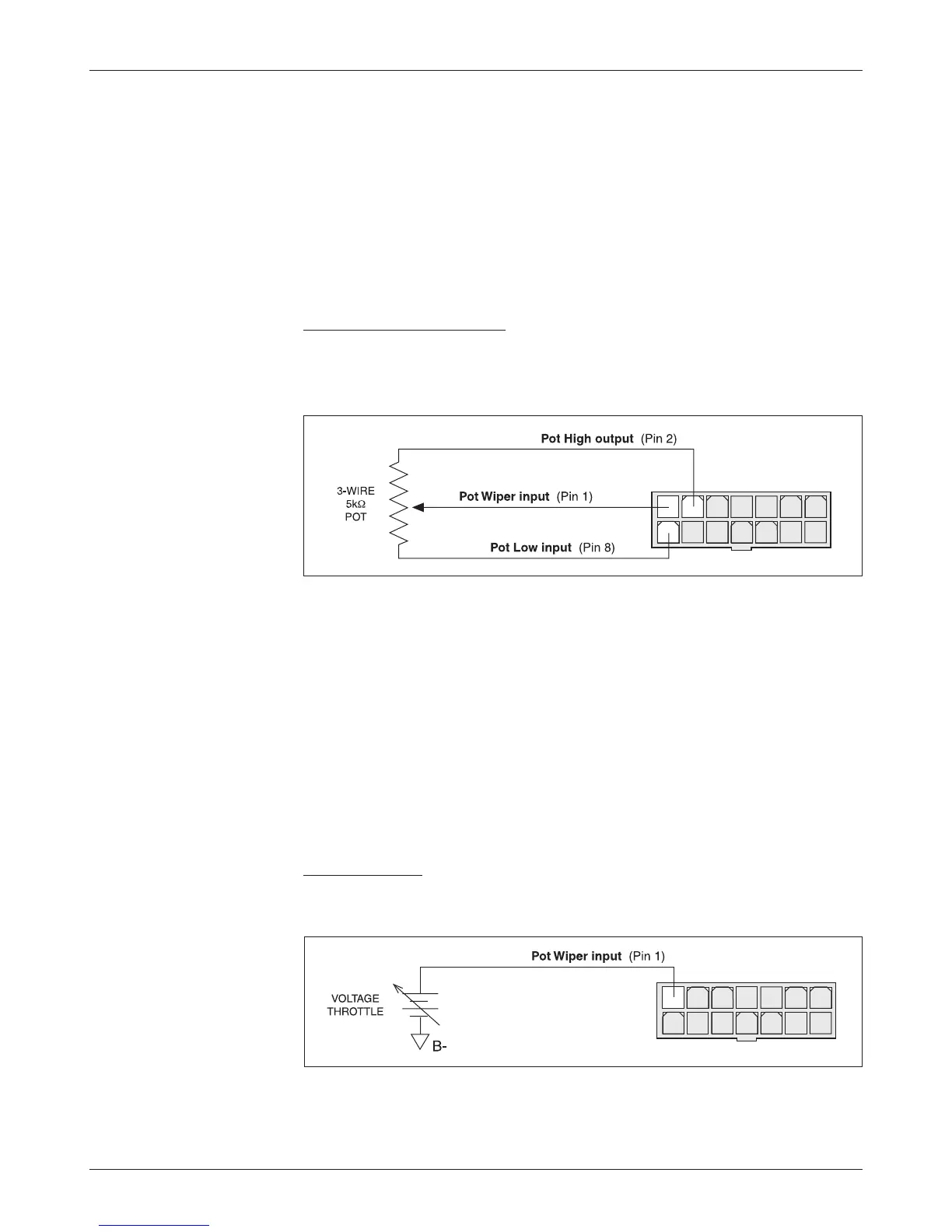
5kΩ, 3-Wire Potentiometer
A 5kΩ, 3-wire potentiometer is shown in the wiring diagram (Figure 3) as
well as in Figure 4. With this throttle, the controller can be programmed for
a Throttle Type 0–4 input signal; see page 15.
Fig. 4 Wiring for 3-wire,
5k
Ω
potentiometer throttle.
For wigwag, inverted wigwag, and unipolar applications, the pot can be
correctly centered within the controller’s neutral band by using the throttle
autocalibration feature (see page 18).
The controller provides full pot fault protection against open or shorted
wires anywhere in the throttle assembly. The overall pot resistance should be
5kΩ ±20%. Values outside this range will trigger a fault condition. If a pot fault
occurs while the vehicle is moving, the controller will decelerate the vehicle to
a smooth stop using the decel rate set by the Key Off Decel parameter. If the
fault is corrected while the throttle is still applied, an HPD fault will be issued
and driving is disabled until throttle is reduced to neutral.
Voltage Throttle
Wiring for a voltage throttle is shown in Figure 5. With this throttle, the con-
troller can be programmed for a Throttle Type 5–9 input signal; see page 15.
1 2 3 4 5 6 7
8 9
10 11 12 13 14
Fig. 5 Wiring for voltage
throttle.
1 2 3 4 5 6 7
8 9
10 11 12 13 14
+
-
VOLTAGE
THROTTLE
Pot Wiper input (Pin 1)
B-
The PotHigh and PotLow parameters are used to set the voltage range of
these throttles. If the pot wiper voltage is higher than the programmed PotHigh