Curtis 1212 Manual
5
2 — INSTALLATION & WIRING
J1 Pin 1 pot wiper
J1 Pin 2 pot high
J1 Pin 3 horn switch
J1 Pin 4 mode switch (open=M1, closed=M2)
J1 Pin 5 keyswitch input (KSI)
J1 Pin 6 speed inhibit
J1 Pin 7 B+
J1 Pin 8 pot low
J1 Pin 9 speed pot
J1 Pin 10 status LED
J1 Pin 11 BDI
J1 Pin 12 reverse switch
J1 Pin 13 B-
J1 Pin 14 push switch
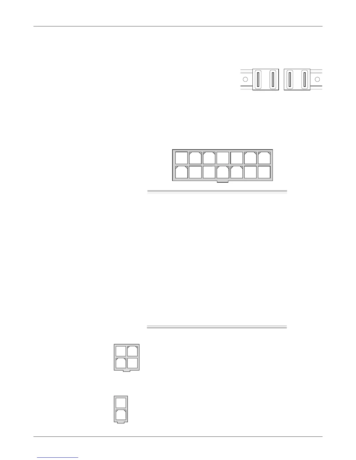
CONNECTIONS: High Current
Four 1/4" Faston terminals are provided for the high current connections.
The motor connections (M1, M2) and battery
connections (
B+, B-) have one terminal each.
CONNECTIONS: Low Current
The low current logic control connections are provided by a 14-pin connector.
The mating connector is a Molex Mini-Fit-Jr. receptacle p/n 39-01-2140 with
appropriate 45750-series crimp terminals.
A 4-pin low power connector is provided for the programmer and
the battery charger. The mating connector is a Molex Mini-Fit-Jr.
receptacle p/n 39-01-2040 with appropriate 45750-series crimp
terminals. (A mating connector is provided with the 1311 handheld
programmer.)
.
A 2-pin low power connector is provided for the electromagnetic brake.
The mating connector is a Molex Mini-Fit-Jr. receptacle p/n 39-01-2020
with appropriate 45750-series crimp terminals.
J1
J2
J2 Pin 1 Rx
J2 Pin 2 B-
J2 Pin 3 Tx/charge inhibit
J2 Pin 4 B+
J3 Pin 1 Brake +
J3 Pin 2 Brake -
J3
1 2 3 4 5 6 7
8 9
10 11 12 13 14