18
Curtis 1220 Manual, Rev. C
3 — PROGRAMMABLE PARAMETERS: Vehicle Configuration Parameters
VEHICLE CONFIGURATION MENU
ALLOWABLE
PARAMETER RANGE DESCRIPTION
Interlock Type 0 / 1
n
Denes which inputs will be used to determine an interlock:
0 = KSI (interlock turns on with keyswitch).
1 = Single NO switch Input.
Sequencing Delay 0 – 5.0 s The sequencing delay feature allows the interlock switch to be cycled
within a set time (the sequencing delay), thus preventing inadvertent
deactivation of the steering control. This feature is useful in applications
where the interlock switch may bounce or be momentarily cycled during
operation.
Fault Output Control
0 / 1 Set this parameter to match your wiring conguration:
0 = Fault output connects to traction controller interlock input.
1 = Fault output connects to traction controller main contactor coil.
Fault Steering Timeout 0.0 – 8.0 s This parameter applies only when a steer fault action of either “Warning
then Shutdown” or “Hold then Shutdown” is triggered (see Table 4,
Troubleshooting Chart). When one of these faults is detected, the Fault
Steering Timeout sets a delay from when either of these fault actions is
set to when the fault output turns off.
direction saved in EEPROM at the last shutdown. The home position is
just at the switch transition period.
Homing Speed 0 – 100 % Denes the speed of the steering motor during the homing function,
as a percentage of the steer motor Max Speed.
The lower the set value of Homing Speed, the more accurate the
homing will be; it is therefore recommended that Homing Speed be set
as low as tolerable. Although higher values will allow the homing function
to be completed more quickly, the results will be less consistent than with
lower values.
Homing Compensation (Deg)
-5.0° – 5.0° This parameter is active only when the Homing Direction Method = 4.
It compensates for homing to zero position from either direction.
FEEDBACK DEVICE: HOMING, cont’d
ALLOWABLE
PARAMETER RANGE DESCRIPTION
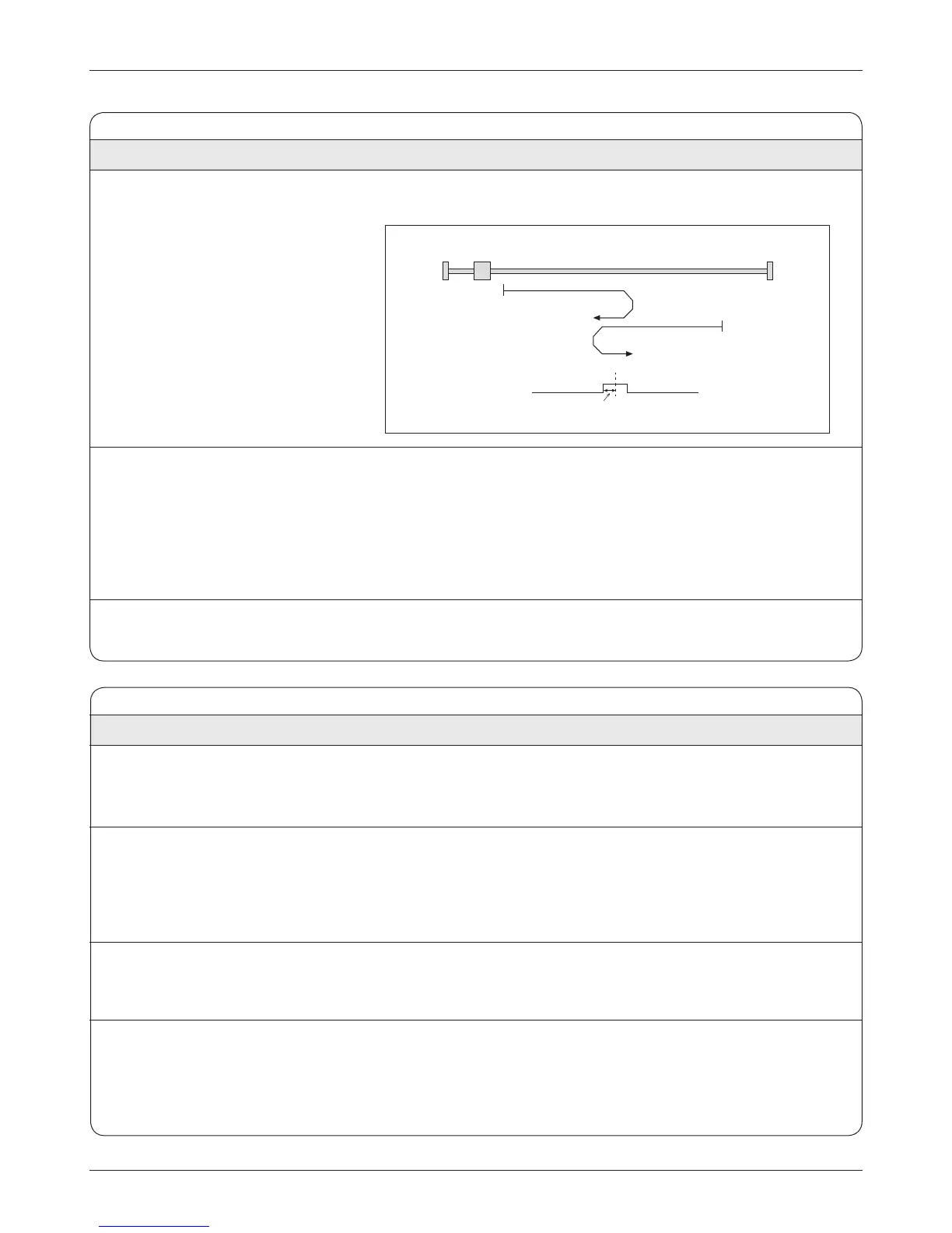
Homing on the center of the positive Home switch (Method 4)
Home Switch
Home Position Center
Homing compensation value