Curtis 1220 Manual, Rev. C
15
3 — PROGRAMMABLE PARAMETERS: Feedback Device Parameters
FEEDBACK DEVICE: ANALOG
ALLOWABLE
PARAMETER RANGE DESCRIPTION
Redundant Input Off / On Denes whether the primary (J1-11) or both (J1-11 and J1-3) position
feedback inputs will be used; see Command Redundant Input, page 11.
Position Left Stop 0 – 5.00 V Denes the position analog wiper voltage when the steer position
feedback is at the left stop (Wheel Position = Left Stop).
Position Center 0 – 5.00 V Denes the position analog wiper voltage when the steer position
feedback device is at the center position (Wheel Position = 0°).
Position Right Stop
0 – 5.00 V Denes the position analog wiper voltage when the steer position
feedback device is at the right stop (Wheel Position = Right Stop).
Position Fault Min 0 – 5.00 V Sets the minimum threshold for the position feedback analog pot input.
If the position wiper voltage goes below this threshhold for 60 ms,
a fault is issued.
Position Fault Max
0 – 5.00 V Sets the maximum threshold for the position feedback analog pot input.
If the position wiper voltage rises above this threshhold for 60 ms,
a fault is issued.
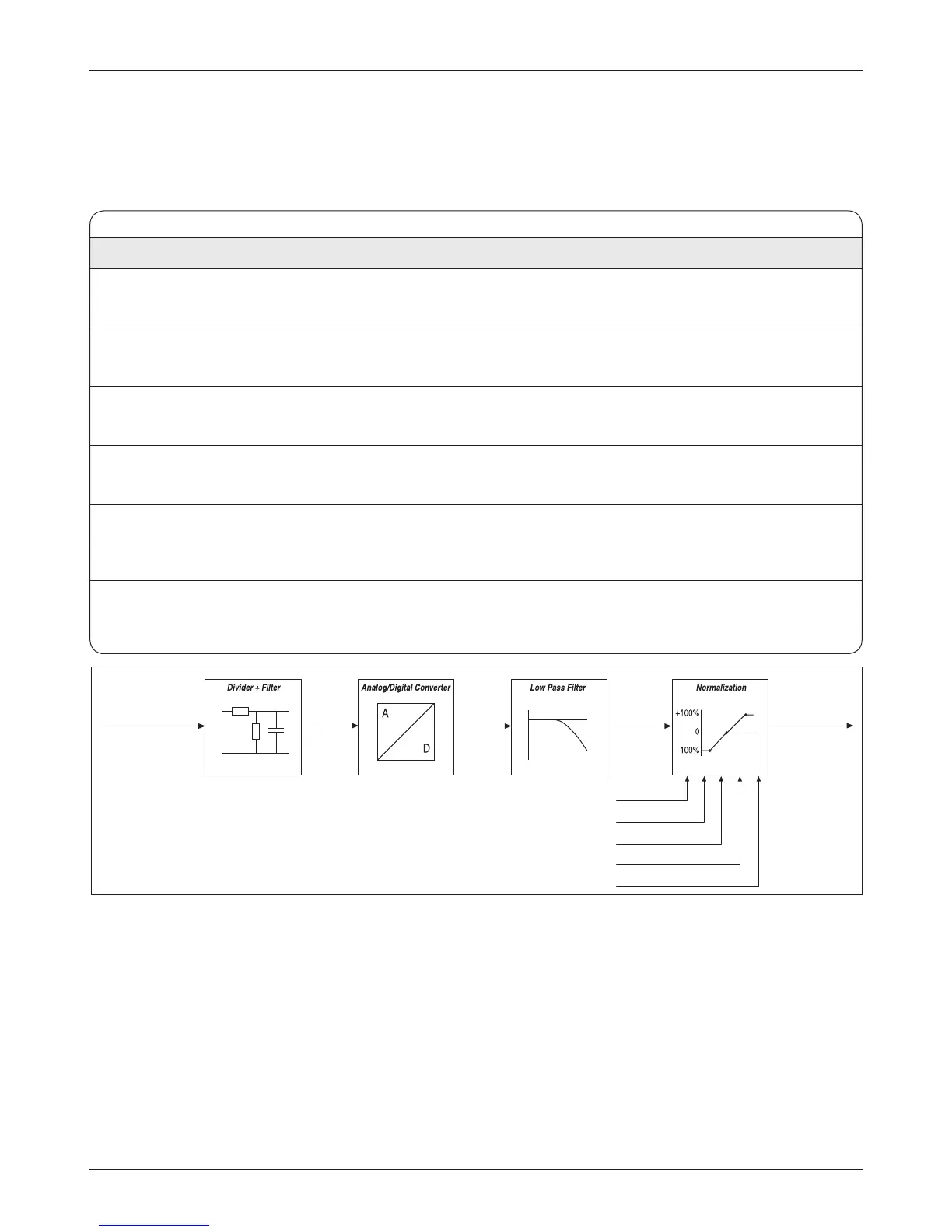
e normalization map takes Position Analog input in volts and maps it to
Wheel Position in percent.
Position Left Stop may be set higher or lower than Position Right Stop.
Position Center must be between Position Left Stop and Position Right Stop.
Assuming Position Left Stop is less than Position Right Stop, the three points of
the normalization map are dened (from left to right in the diagram above) as:
X = Position Left Stop and Y = Left Stop (deg)
X = Position Center and Y = 0%
X = Position Right Stop and Y = Right Stop (deg).
e wheel position is aligned to the current steer command position upon inter-
lock. e left stop, center, and right stop points are programmable parameters.
Angular rotation is limited by means of programmable left stop (deg) and right
stop (deg) parameters in the Command Map.
Fig. 6 Position feedback signal ow, with analog pot.
Position Analog 1 Input
(pin J1-11)
[3.3V]
[12 bits]
Position Left
Position Center
Position Right
Wheel Position
Left Stop (deg)
Right Stop (deg)