Curtis 1220 Manual, Rev. C
7
2 — INSTALLATION & WIRING: Controller Wiring
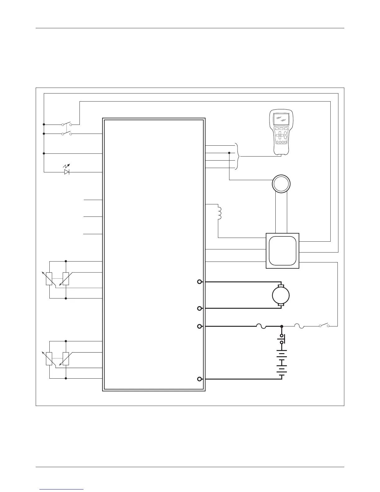
ese wiring diagrams (Figs. 3a, 3b) show generic applications and may not
fully meet the requirements of your system. You may wish to contact your local
Curtis representative to discuss your particular application.
Fig. 3b Basic wiring diagram, using position feedback pots for feedback device.
1220 CONTROLLER
J1-6
J1-7
KSI
J1-5
J3-2
Interlock Input
J1-4
MOTOR
J1-1
Status LED
J3-1
J2-3
J2-2
J2-1
KEYSWITCH
Fault Output
B+
GND
Rx1
M1
M2
BATTERY
(24V)
B+
B-
Tx1
EMERGENCY
STOP
+5V
J1-12
J1-8
Rx2
Steering Angle
Output
CURTIS
AC
TRACTION
CONTROLLER
J1-13
J1-14
Command Analog 2
Command Analog 1
+5V
Command Pot Low
POSITION FEEDBACK
POTS
STEER COMMAND
POTS
J1-7 I/O GND
TRACTION
MAIN
CONTACTOR
COIL
J1-9 Interlock
J1-1 KSI
SW1/ANA1 J1-24
Tx J1-28
J1-13 Coil Return
INTERLOCK SWITCH
STATUS LED
Position Analog 1
J1-9
Feedback Pot Low
J1-2
M
Main Driver J1-6
840
+12V J1-25
J1-8 GND
Power
Supply Input
J1-5
Receive J1-6
PROGRAMMER
J2-4
123xE/1298
POWER
FUSE
CONTROL
FUSE
J1-11
J1-7
J1-3
J1-10
Position Analog 2