6
Curtis 1220 Manual, Rev. C
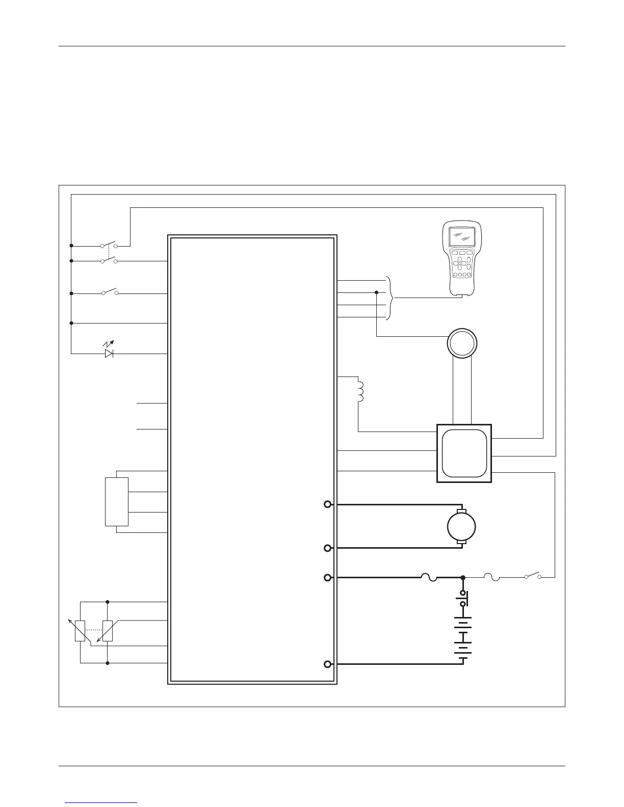
Fig. 3a Basic wiring diagram, using motor encoder for feedback device.
2 — INSTALLATION & WIRING: Controller Wiring
CONTROLLER WIRING
As shown in the wiring diagrams (Figs. 3a, 3b), the 1220’s keyswitch power
must go through the traction controller so that when the keyswitch is turned
o both controllers turn o. e fault output (Pin J3-1) must be able to shut
down the traction system in the case of a serious fault, in order to meet inter-
national safety requirements.
J1-6
J1-7
KSI
J1-5
Home Switch
J3-2
J1-11
Interlock Input
J1-4
MOTOR
J1-1
Status LED
J3-1
J2-3
J2-2
J2-1
KEYSWITCH
Fault Output
B+
GND
Rx1
M1
M2
BATTERY
(24V)
B+
B-
Tx1
EMERGENCY
STOP
+5V
J1-7
J1-12
J1-8
Rx2
Steering Angle
Output
CURTIS
AC
TRACTION
CONTROLLER
J1-13
J1-14
Command Analog 2
Command Analog 1
+5V
Command Pot Low
STEER
MOTOR
ENCODER
STEER COMMAND
POTS
J1-7 I/O GND
TRACTION
MAIN
CONTACTOR
COIL
J1-9 Interlock
J1-1 KSI
SW1/ANA1 J1-24
Tx J1-28
J1-13 Coil Return
INTERLOCK SWITCH
STATUS LED
Encoder
Phase A
J1-2
Encoder
Phase B
J1-9
Feedback
Pot Low
J1-10
HOME SWITCH
J1-3
M
Main Driver J1-6
840
+12V J1-25
J1-8 GND
Power
Supply Input
J1-5
Receive J1-6
PROGRAMMER
J2-4
123xE/1298
POWER
FUSE
CONTROL
FUSE