Curtis 1220 Manual, Rev. C
13
3 — PROGRAMMABLE PARAMETERS: Command Map Parameters
COMMAND DEVICE: COMMAND MAP
ALLOWABLE
PARAMETER RANGE DESCRIPTION
P1–P6 Input -100.0 – 100.0 % These six parameters individually dene the steer command input
(in %) for the P1, P2, P3, P4, P5, and P6 Inputs.
Left Stop (deg)
-120.0° – 0.0° These eight parameters dene the steer command output (in degrees)
of the steer command map.
Left Stop (deg)
P1–P3 Output (deg)
-120.0° – 0.0° P1 Output (deg)
P2 Output (deg)
P3 Output (deg)
P4–P6 Output (deg)
0.0° – 120.0° P4 Output (deg)
P5 Output (deg)
P6 Output (deg)
Right Stop (deg)
0.0° – 120.0° Right Stop (deg)
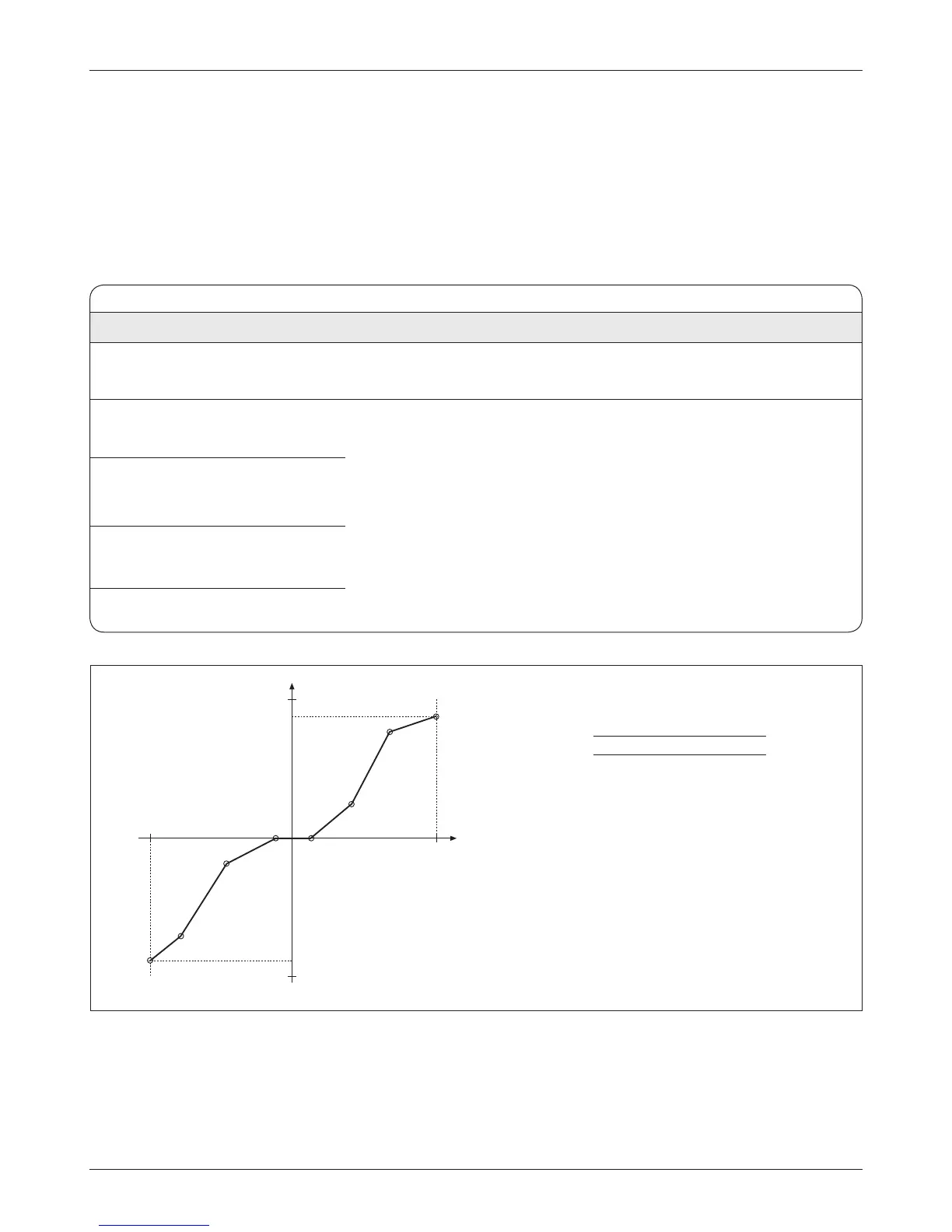
Fig. 5 Steer command map.
X Y
A -100% Left Stop (deg)
B P1 input P1 Output (deg)
C P2 input P2 Output (deg)
D P3 input P3 Output (deg)
E P4 input P4 Output (deg)
F P5 input P5 Output (deg)
G P6 input P6 Output (deg)
H 100% Right Stop (deg)
The map in this example is set up to provide a deadband
in the center (points D and E) and less sensitivity at the
ends (between A and B, and between G and H).
Resulting Output
Input
100%
-100%
-120°
120°
A
B
C
D E
F
G
H
The steer command map is shaped by points A – H.
A command map is used in the input command signal ow to compensate for
steering geometry dierences between vehicles (steered wheel on the left side,
middle, or right side).
e command map menu contains 14 parameters dening an 8-point
map that modies the steer command input. e rst point (Left Stop (deg))
always denes the steer command input of -100% and the last point (Right
Stop deg)) always denes the steer command input of 100%.
Although any map shape can be set up, it is recommended that the map al-
ways be set so that a Steer Command of zero % equals a Steer Command
(deg) of zero.