Curtis 1220 Manual, Rev. C
5
2 — INSTALLATION & WIRING: High Current Connections
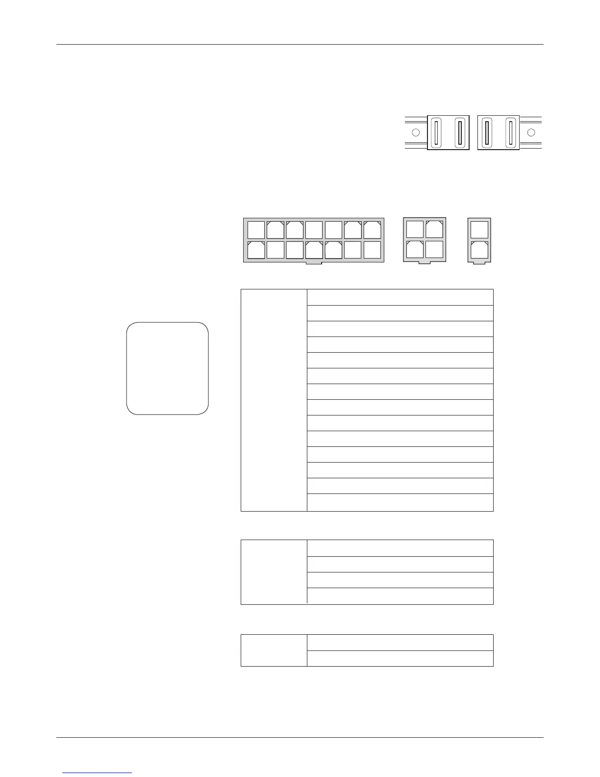
CONNECTIONS: High Current
Four 1/4” Faston terminals are provided for the high current connections.
e motor connections (
M1, M2) and battery
connections (
B+, B-) have one terminal each.
CONNECTIONS Low Current
e low current connections are made through three connectors: J1, J2, and J3.
J1 J2 J3
M1 M2 B- B+
1 Status LED
2 Steer Motor Encoder Phase A
3 Position Analog 2
4 Interlock Input
5 KSI
6 Command Analog 1
7 +5V
8 Rx2 (from traction controller)
9 Steer Motor Encoder Phase B
10 Feedback Pot Low
11 Position Analog 1
12 Steering Angle Output
13 Command Analog 2
14 Command Pot Low
1 Rx1 (from programmer)
2 GND
3 Tx1 (to programmer / 840)
4 B+
1 Fault Output
2 Home Switch
J1
14-pin Molex
39-28-8140
1 2 3 4 5 6 7
8 9 10 11 12 13 14
1 2
3 4
1
2
J2
4-pin Molex
39-28-8040
J3
2-pin Molex
39-28-8020
Mating connectors:
Molex Mini-Fit-Jr
receptacle p/n
J1 39-01-2140
J2 39-01-2040
J3 39-01-2020
with appropriate
45750-series
crimp terminals.