10
Curtis 1220 Manual, Rev. C
3 — PROGRAMMABLE PARAMETERS
3
PROGRAMMABLE PARAMETERS
e 1220 controller has a number of parameters that can be programmed using
a Curtis 1313 handheld programmer or 1314 Programming Station. e pro-
grammable parameters allow the steering performance to be customized to fit
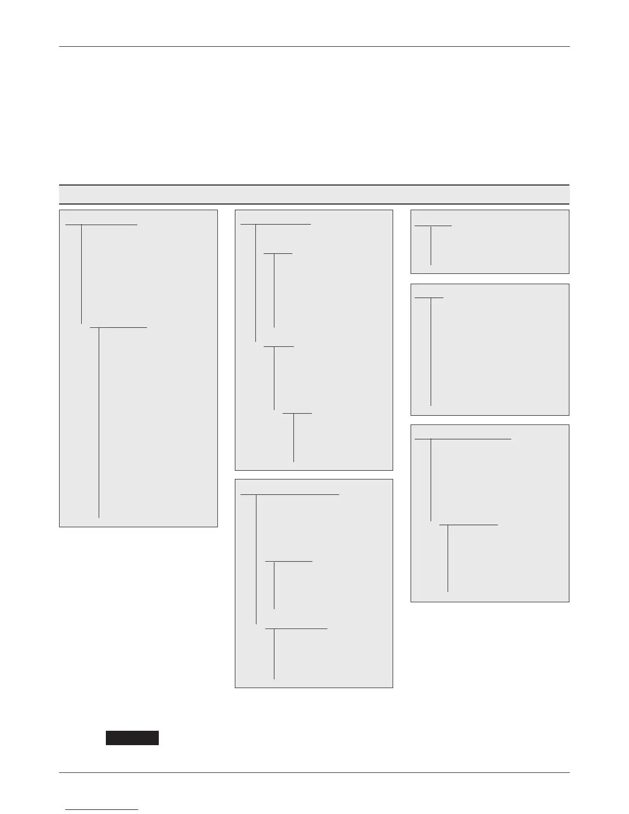
the needs of specific applications. e programmable parameters are grouped
into nested hierarchical menus, as shown in Table 1.
We strongly urge you to read Section 5, Initial Setup, before adjusting any of the
parameters. Even if you opt to leave most of the parameters at their default settings,
it is imperative that you perform the procedures outlined in Section 5, which
set up the basic system characteristics for your application.
+
CAUTION
FEEDBACK DEVICE ..................... p. 14
—Position Feedback Device
—Analog ........................... p. 15
—Redundant Input
—Position Left Stop
—Position Center
—Position Right Stop
—Position Fault Min
—Position Fault Max
—Encoder .......................... p. 16
—Encoder Steps
—Swap Encoder Direction
—Encoder Fault Check
—Center Offset (deg)
—Homing ................... p. 17
—Homing On Interlock
—Homing Direction Method
—Homing Speed
—Homing Compensation (deg)
VEHICLE CONFIGURATION .......... p. 18
—Interlock Type
—Sequencing Delay
—Fault Output Control
—Fault Steering Timeout
—Relay Driver .................... p. 19
—Main On Interlock
—Pull-In Voltage
—Holding Voltage
—Open Delay
—Traction Settings .............. p. 19
—Traction Motor Max Speed
—Interlock Enable Speed
—Speed Limit Angle (deg)
—Steering Angle Output Interlock
CURRENT .................................. p. 20
—Drive Current Limit
—Regen Current Limit
—Boost
MOTOR ..................................... p. 20
—Gear Ratio
—Max Speed
—Stall Steering Speed
—Stall PWM
—Stall Timeout
—Current Rating
—Max Current Time
—Cutback Gain
MOTOR CONTROL TUNING .......... p. 21
—Following Error Tolerance (deg)
—Following Error Time
—Position Kp
—Velocity Kp
—Velocity Ki
—Sensitivity Map ................ p. 22
—LS Sensitivity
—HS Sensitivity
—Low Speed
—Mid Speed
—High Speed
COMMAND DEVICE .................... p. 11
—Redundant Input
—Command Analog Left
—Command Analog Center
—Command Analog Right
—Command Analog Fault Min
—Command Analog Fault Max
—Command Map ................. p. 13
—Left Stop (deg)
—P1 Input
—P1 Output (deg)
—P2 Input
—P2 Output (deg)
—P3 Input
—P3 Output (deg)
—P4 Input
—P4 Output (deg)
—P5 Input
—P5 Output (deg)
—P6 Input
—P6 Output (deg)
—Right Stop (deg)
Table 1 Programmable Parameter Menus