4
Curtis 1220 Manual, Rev. C
2 — INSTALLATION & WIRING
2
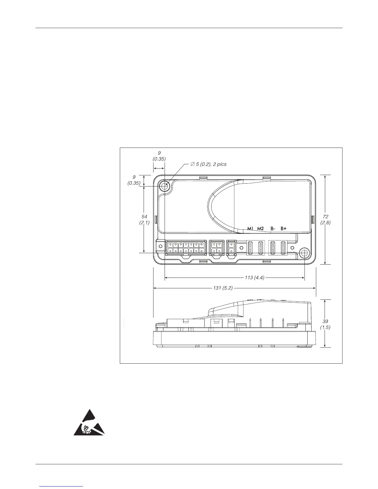
Fig. 2 Mounting
dimensions, Curtis 1220
motor controller.
Dimensions in millimeters (and inches)
INSTALLATION AND WIRING
MOUNTING THE CONTROLLER
e 1220 controller can be oriented in any position, but the mounting location
should be carefully chosen to keep the controller clean and dry. If a clean, dry
mounting location cannot be found, a cover must be used to shield the
controller from water and contaminants.
e outline and mounting hole dimensions are shown in Fig. 2. e con-
troller should be mounted by means of the two mounting holes at the opposing
corners of the heatsink, using M4 (#8) screws.
You will need to take steps during the design and development of your
end product to ensure that its EMC performance complies with applicable
regulations; suggestions are presented in Appendix A.
e 1220 controller contains ESD-sensitive components. Use appro-
priate precautions in connecting, disconnecting, and handling the controller.
See installation suggestions in Appendix A for protecting the controller from
ESD damage.