14
Curtis 1220 Manual, Rev. C
3 — PROGRAMMABLE PARAMETERS: Feedback Device Parameters
FEEDBACK DEVICE
ALLOWABLE
PARAMETER RANGE DESCRIPTION
Position Feedback Device 0 – 2 Set this parameter to match the type of device you will be using
for position feedback:
0 = Analog sensor.
1 = Polarity encoder.
2 = Quadrature encoder.
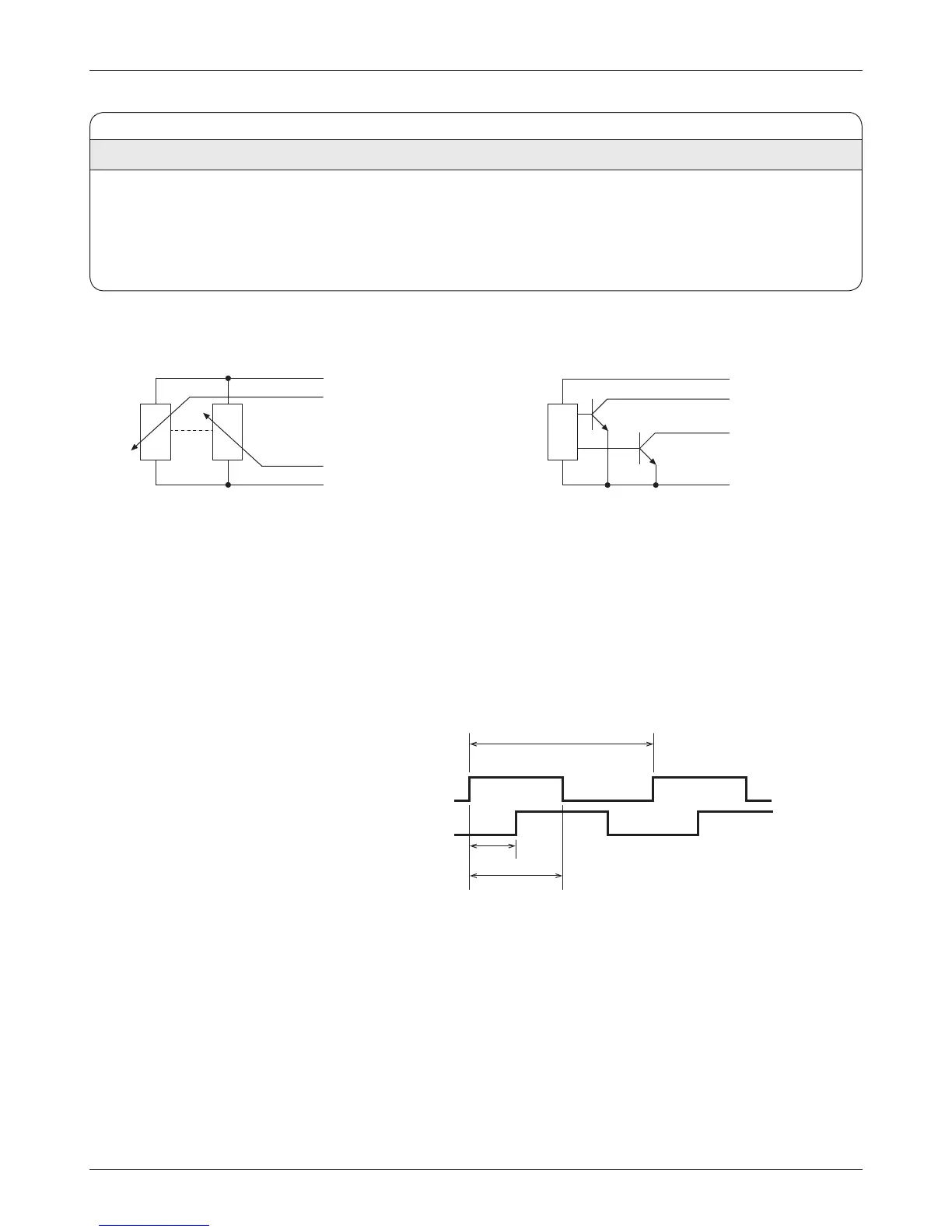
Encoder Phase A
Feedback Pot Low
+5V
Position Encoder Input
(Position Feedback Device = 1 or 2)
Encoder Phase B
If encoder position feedback is used, an encoder and a home switch are required.
e electrical requirements for the encoder are as shown.
Position Analog 1(primary)
Feedback Pot Low
+5V
Position Analog Input
(Position Feedback Device = 0)
Position Analog 2 (redundant)
Channel A
Channel B
360° electrical (1 cycle)
> 66 μs
180° ±18°
90° ±30°