Curtis 1244 Manual, Rev. E
7
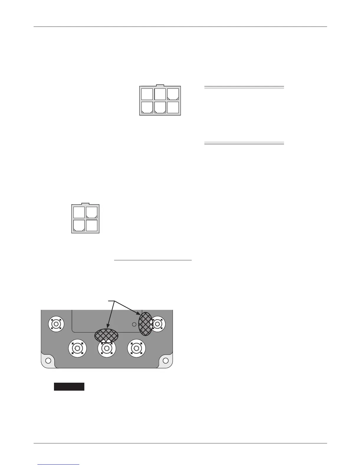
F1
F2
STATUS
LED
CABLE-FREE ZONES
A 6-pin low power Molex connector is provided for the CAN Bus interface.
However, the CAN Bus option must be specified for this interface to be active.
e mating connector is a Molex Mini-Fit Jr. p/n 39-01-2065 using type 5556
terminals.
Pin 1 +15V supply (limited)
Pin 2 ground return (B-)
Pin 3 CAN H I/O line
Pin 4 L termination
Pin 5 H termination
Pin 6 CAN L I/O line
Power cables must not be routed over the indicated areas. Otherwise they
may interfere with the proper operation of sensitive electromagnetic compo-
nents located underneath.
e +15V supply should only be used with the CAN system or speed sensor
and not to power any other external systems.
e L and H terminations provide a 120Ω termination impedance for
the CAN H I/O and CAN L I/O inputs if necessary. Refer to the Curtis CAN
Protocol Document to determine the proper termination for a given application.
A 4-pin low power connector is provided for the handheld 1313 programmer
or 1314 PC programming station. A complete programmer kit, including the
appropriate connecting cable, can be ordered from Curtis.
If a programmer is already available but has an incompatible cable, the
1244 mating cable can be ordered as a separate part: Curtis p/n 16185.
High Current Connections
Five tin-plated solid aluminum bus bars are provided for the high current connec-
tions to the battery
(B+ and B-), the motor armature (M-), and the motor field (F1
and
F2). ese bus bars incorporate threaded mounting studs designed to accept
mounting bolts. e
B+, B-, and M- bus bars are threaded to accept M8 bolts to
bolts to a depth of 5/8". is simplifies the assembly
and reduces the mounting hardware necessary for the
power connections. e tightening torque applied to
the bolts should not exceed 16.3 N·m (12 ft-lbs) for
the M6 bolts or 20 N·m (15 ft-lbs) for the M8 bolts.
Exceeding these specifications could damage the bus
bars’ internal threads, resulting in loose connections.
2 — INSTALLATION & WIRING: Controller
a depth of 3/4". e F1 and F2 bus bars are threaded to accept M6
☞
CAUTION