12
Curtis 1244 Manual, Rev. E
14 1315161718192021222324
12 11 10 9 8 7 6 5 4 3 2 1
14 1315161718192021222324
12 11 10 9 8 7 6 5 4 3 2 1
+
-
+
B-
Pin 15
0–5V Input
PIN KEY
Pin 15
Pin 14
0–5V Input
Pot Low
PIN KEY
SENSOR GROUND
SENSOR OUTPUT (0–5V)
SENSOR
2 — INSTALLATION & WIRING: Throttle
wigwag-style control—without the necessity of providing independent forward
and reverse input signals—see rottle Type 4.
If the total resistance between Pins 14 and 16 is greater than 7.5 kΩ, the
controller’s 4.4 V upper fault limit will be exceeded and the controller output
will be disabled. is provides broken wire protection, and also serves as an
indication that the potentiometer’s nominal value has increased and the pot
needs to be replaced.
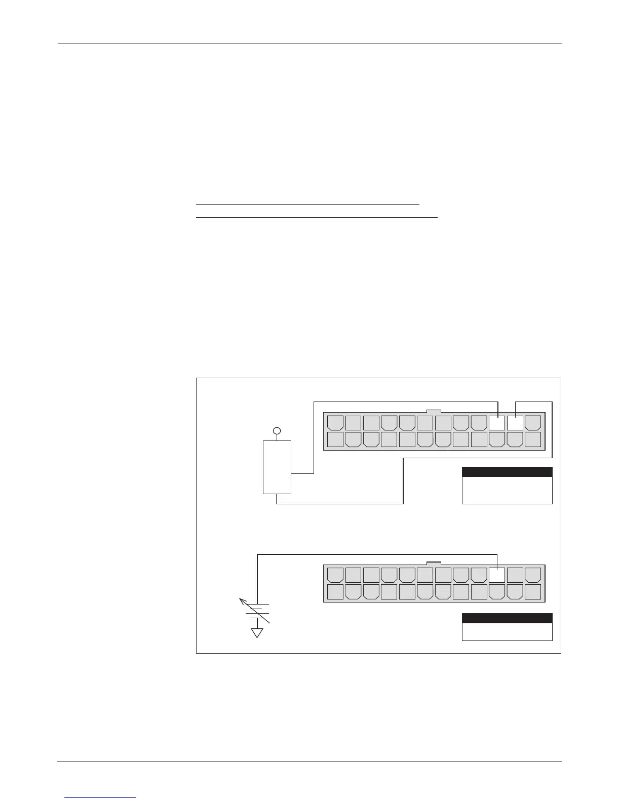
0–5V, 3-Wire Potentiometer, Current Source,
and Electronic Single-Ended Throttles (“Type 2”)
With these throttles (“Type 2” in the programming menu) the controller looks
for a voltage signal at the wiper input (Pin 15). Zero speed will correspond to
0V and full speed to 5 V. A 3-wire pot, voltage source, voltage sensor, or current
source can be used with this throttle type. e wiring for each is slightly dierent.
0–5V rottle
Two ways of wiring the 0–5V throttle are shown in Figure 6. e active range
for this throttle is from 0.2V (at 0% rottle Deadband) to 5.0 V (at 100%
rottle Max), measured relative to B-.
Fig. 6 Wiring for
0–5V throttles (“Type 2”).
(b) Ground-referenced
0–5V throttle
(a) Sensor-referenced
0–5V throttle