Curtis 1244 Manual, Rev. E
13
2 — INSTALLATION & WIRING: Throttle
3-Wire Potentiometer (1k
Ω
–10k
Ω
) rottle
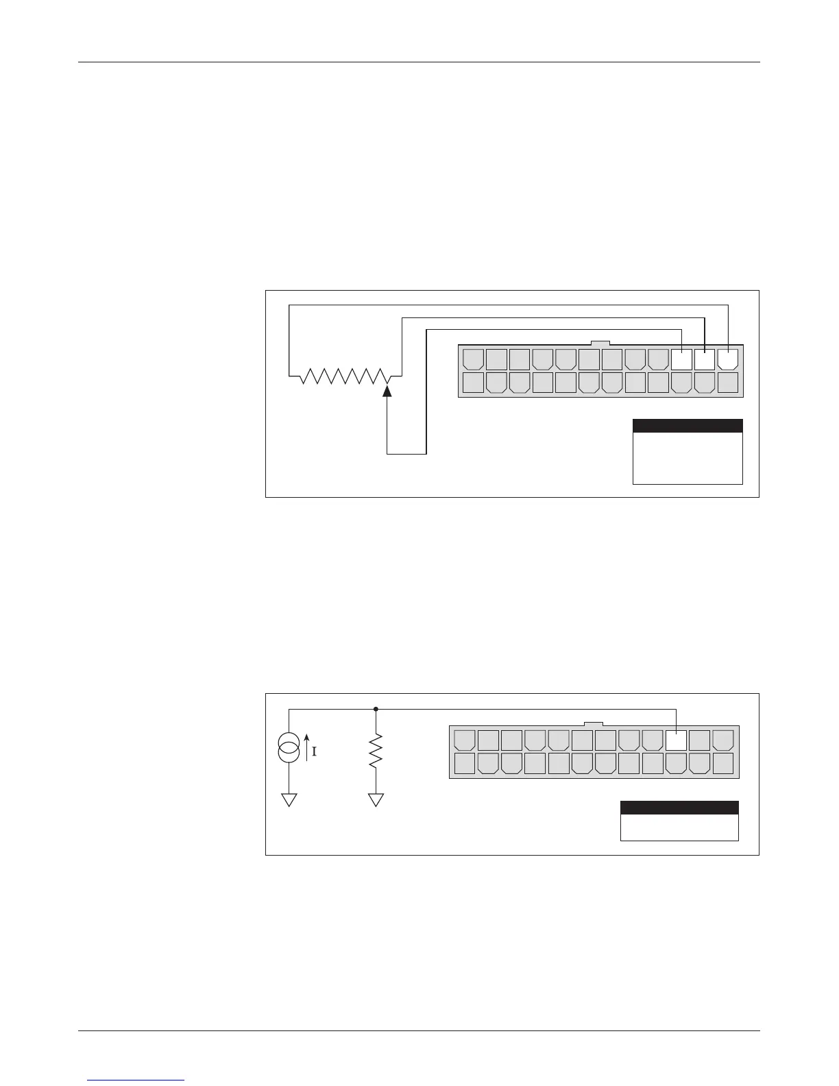
e 3-wire potentiometer is used in its voltage divider mode, with the voltage
source and return being provided by the 1244 controller. Pot High (Pin 13)
provides a current limited 5V source to the pot, and Pot Low (Pin 14) provides
the return path. e pot wiper is then connected to the Wiper Input (Pin15).
If a 3-wire pot is used in the application, the controller will provide full throttle
fault protection in accordance with EEC requirements. Potentiometers with total
resistance values between 1kΩ and 10kΩ can be used with rottle Type 2.
Wiring is shown in Figure 7.
Fig. 7 Wiring for 3-wire
potentiometer throttle
(“Type 2”).
14 1315161718192021222324
12 11 10 9 8 7 6 5 4 3 2 1
OFFON
1kΩ–10kΩ
Pin 15
Pin 14
Pin 13
Pot Wiper
Pot Low
Pot High
PIN KEY
Current Sources As rottles
A current source can also be used as a throttle input, as shown in Figure 8. A
resistor, R
throttle
, must be used to convert the current source value to a voltage.
e resistor should be sized to provide a 0–5V signal variation over the full
current range.
Fig. 8 Wiring for current
source throttle (“Type 2”).
14 1315161718192021222324
12 11 10 9 8 7 6 5 4 3 2 1
R
throttle
B-B-
source
Pin 15
0–5V Input
PIN KEY
I