User Guide DDOC0199-000-A9
1-Slot Data Transport System (CSfC) 5 - 2 Installation
© 2024 Curtiss-Wright Defense Solutions Revision 0.0
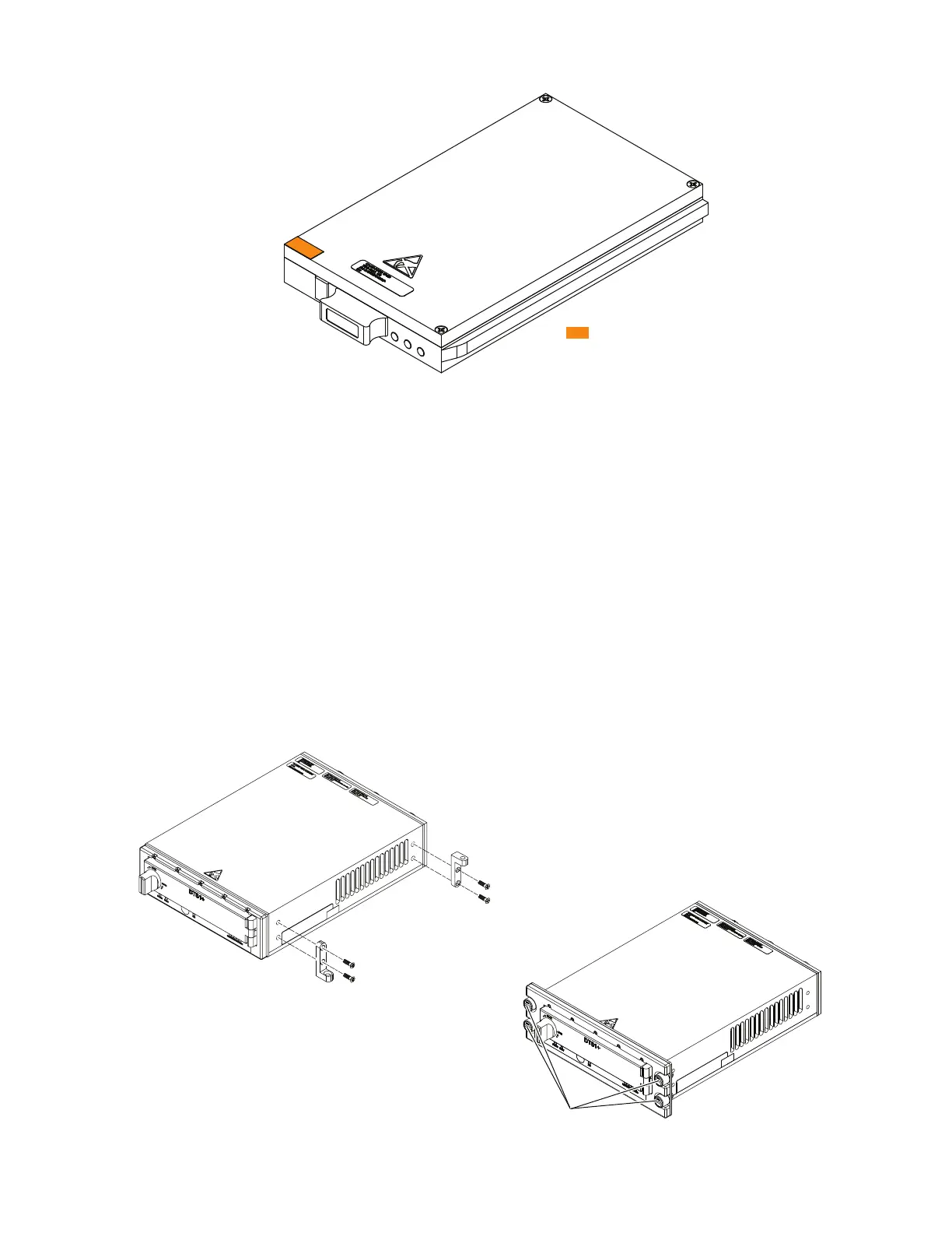
Figure 5.2 RMC Module Anti-Tamper Label Location
5.3 Mounting
Mounting environment considerations should include operating temperature limits, humidity, and
vibration limits. Other considerations should include clearance for mounting hardware, cables, and
safe installation or removal of the DTS1+ CSfC chassis from its mounting structure. Precautions
should be taken when cables are routed around structures that could cause excessive abrasion,
such as around the corner of vibrating equipment.
Installation of the DTS1+ CSfC can put an increased demand on cooling systems by raising
ambient air temperatures. Evaluate changes in airflow obstructions and temperatures around
equipment and possible detrimental surface temperatures due to conducted heat. See paragraph
A.5 Environmental, EMI, Electrical Specificationsfor thermal limit specifications.
Mechanical mounting of the DTS1+ CSfC requires compliance to MIL-STD MS25212. This will
require the acquisition of the appropriate mounting components and precise installation per the
selected platforms mounting specifications. Two mounting methods (Figure 5.3) provide secure
attachment to a platform: standard platform mounting brackets or a Dzus mount. If installation and
removal of the RMC module is desired while the DTS1+ CSfC remains mounted, be sure to allow
clearance (Figure 5.4) for the door to open and the RMC module to be positioned in front of the
DTS1+ CSfC.
Figure 5.3 DTS1+ CSfC Chassis Mounting
Anti-Tamper Label Locations
DDOC0199-0044
DDOC0199-0007
DTS1+ CSfC
Standard Mount
DTS1+ CSfC
DZUS Mount
Dzus Fasteners
L-Bracket
(Platform Orientation)
L-Bracket
(Hanging Orientation)