User Guide DDOC0199-000-A9
1-Slot Data Transport System (CSfC) 8 - 1 Operation
© 2024 Curtiss-Wright Defense Solutions Revision 2.0
Operation
CAUTION
CONFIGURATION ACCESS. Before attempting to setup or configure the DTS1+ CSfC, the Write-
Enable switch MUST be in the READ-WRITE position.
Before attempting to configure the DTS1+ CSfC, set the write-enable switch to the READ-WRITE
position. Refer to paragraph 4.2.2 Write-Enable Switch for detailed location information. After
configuring the unit, set the write-enable switch to the READ position.
NOTE
Throughout this section, yellow highlighted text is used to denote user-defined or software-gener-
ated inputs. Green highlighted text is used to show changes in values, settings, or responses due
to implementation of a software command.
8.1 Setup / Connections
NOTE
The DTS1+ CSfC is powered by a user-supplied 28 VDC power supply and does not have a power
switch of its own. The DTS1+ CSfC is powered up by turning on the 28 VDC supply.
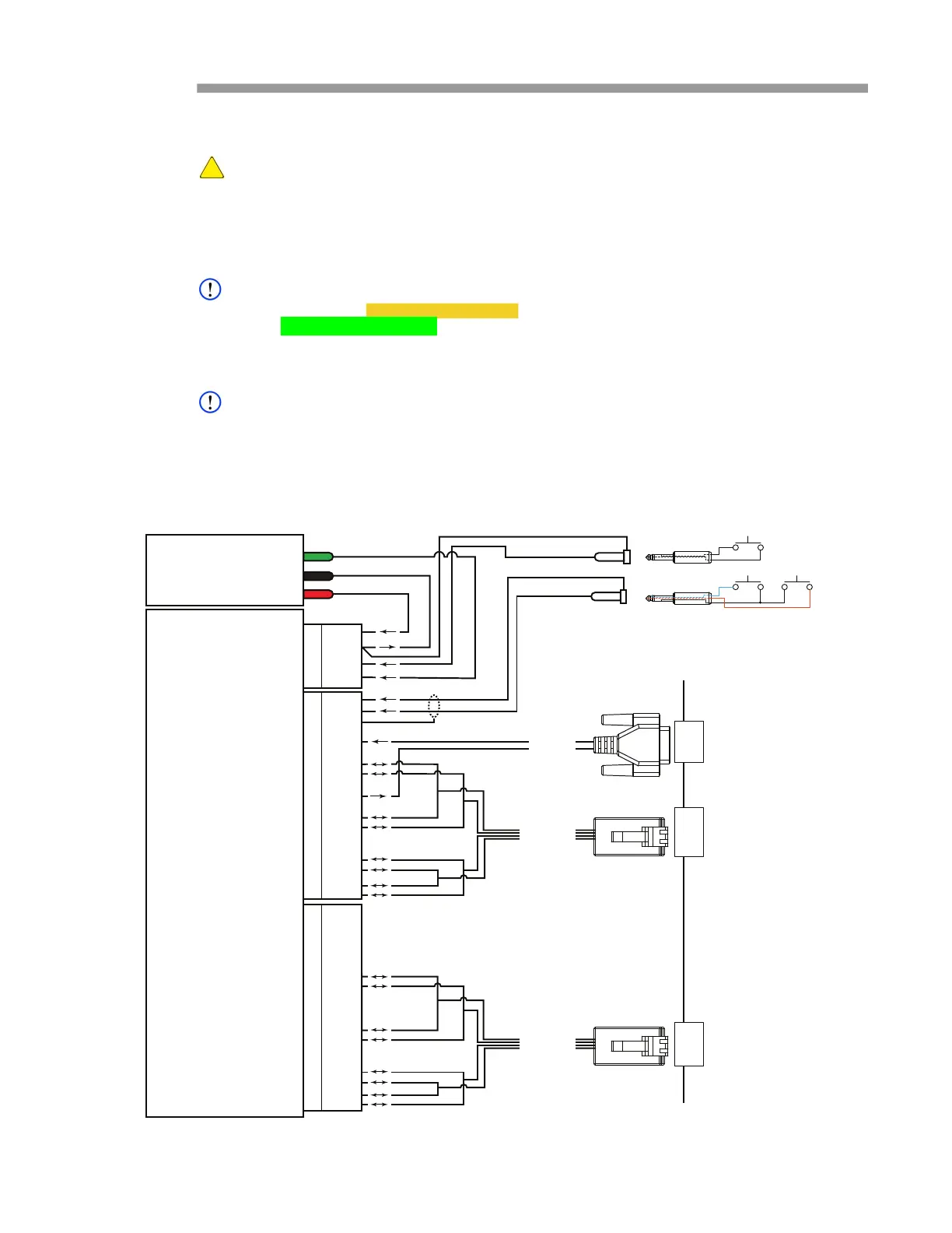
1. If not previously accomplished, connect cables to DTS1+ CSfC connectors (Figure 8.1).
2. If not previously accomplished, connect cables to terminal / PC connectors.
3. Turn on 28 VDC power supply.
Figure 8.1 DTS1+ CSfC Test Setup
28 VDC
POWER
SUPPLY
GND
28 VDC RTN
28 VDC
DDOC0199-0016
4
3
2
1
4
3
2
1
J1
P4
P2
P3
J1
J2
6
5
4
3
2
1
12
11
10
9
8
7
13
19
18
17
16
15
14
6
5
4
3
2
1
12
11
10
9
8
7
13
19
18
17
16
15
14
J2
P2
P2
6
5
4
3
2
1
12
11
10
9
8
7
13
19
18
17
16
15
14
6
5
4
3
2
1
12
11
10
9
8
7
13
19
18
17
16
15
14
J3
C1
B1
A1
D1
ZEROIZE
POWER DISABLE
RESET
RS-232
ETHERNET
C2
B2
A2
D2
ETHERNET
NETWORK / TERMINAL / PC
SERIAL PORT
ETHERNET PORT
ETHERNET PORT
DTS1+ CSfC
P1
P1
P1
J1