User Guide DDOC0199-000-A9
1-Slot Data Transport System (CSfC) 5 - 3 Installation
© 2024 Curtiss-Wright Defense Solutions Revision 0.0
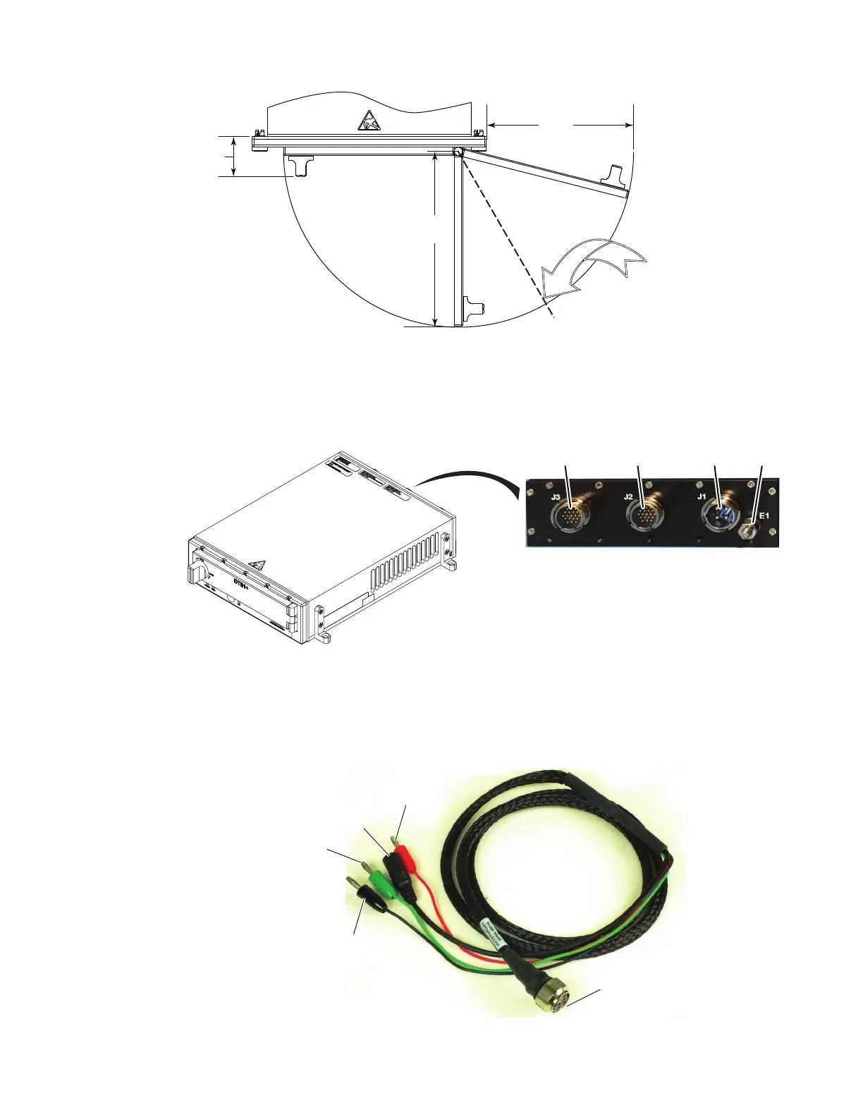
Figure 5.4 DTS1+ CSfC Required Door Clearance
5.4 Cables
All connections to the DTS1+ CSfC are on the rear panel (Figure 5.5). Be sure the power supply is
off when making connections.
Figure 5.5 DTS1+ CSfC Rear Panel Connectors
5.4.1 Power Cable
The Power Lab Cable (VS-DTS1PWRCAB-0) (Figure 5.6) is used to make power connections to
the DTS1+ CSfC. The DTS1+ CSfC requires an input power of +28 volts and ground. Refer to
paragraph B.1 Power Connector J1 / Power Lab Cable for connector pin signal information.
Figure 5.6 Power Lab Cable
DDOC0199-000
6
0.994
(25.24)
4.00
(101.6)
3.25
(82.5)
NOTE:
Access Door Must Be Able
To Be Opened 120° In Order
To Install / Remove RMC.
DDOC0199-0009
Ethernet
RS-232
Ethernet
Power Ground
DDOC0199-0010
Connector P1
28 VDC
Power Disable Input
(Audio Jack)
Ground
28 VDC Return