Cybex 750T Treadmill Service Manual
Service
Page 4-22
6. Attach the display overlay.
A. Remove the paper backing from the new display overlay.
B. Slide the ribbon cable through the slot.
C. Carefully place the display overlay in position within the indentation on the console front and
firmly rub the display overlay so that it adheres to the console.
D. Connect the lower switch membrane to the display board.
7. Attach the display boards.
A. Place the lower display board in position on the front console.
B. Using a Phillips screwdriver, secure the seven screws that hold the lower display board to the
console. See Figure 27.
C. Place the upper display board in position on the front console.
D. Using a Phillips screwdriver, secure the three screws that hold the upper display board to the
console. See Figure 27
Contact Heart Rate Grips
Tools Required
• Phillips screwdriver
• Needle nose pliers
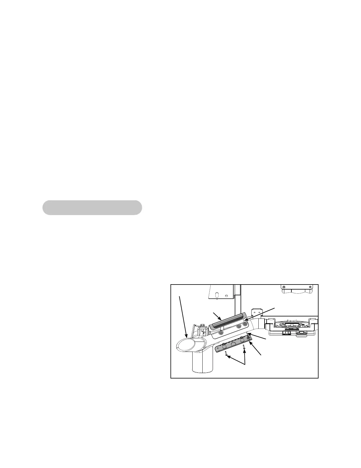
8. Remove the heart rate grips.
A. Using a Phillips screwdriver, remove
the two screws from the bottom grip.
See Figure 28.
B. Gently pull the top and bottom grip off
of the handrail. See Figure 28.
C. Using a needle nose pliers, carefully
disconnect the heart rate wire from
each grip.
9. Install the heart rate grips.
A. Using the needle nose pliers, carefully
connect the heart rate wire to each
grip. NOTE: Ensure that the red heart
rate wire is connected to the top grip
and the black heart rate wire is connected to the bottom grip. See Figure 28.
B. Place the top and bottom grip in the correct position on the handrail. See Figure 28.
C. Using a Phillips screwdriver, remove the two screws from the bottom grip. See Figure 28.
Figure 28
Handrail
Screws (2)
Top
Grip
Heart Rate Wire
Front (Red)
Bottom Grip
Heart Rate Wire
Rear (Black)