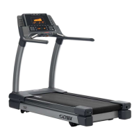
Cybex 750T Treadmill Service Manual
Service
Page 4-25
Display Cable
Tools Required
• Wire cutters
16. Remove the display cable.
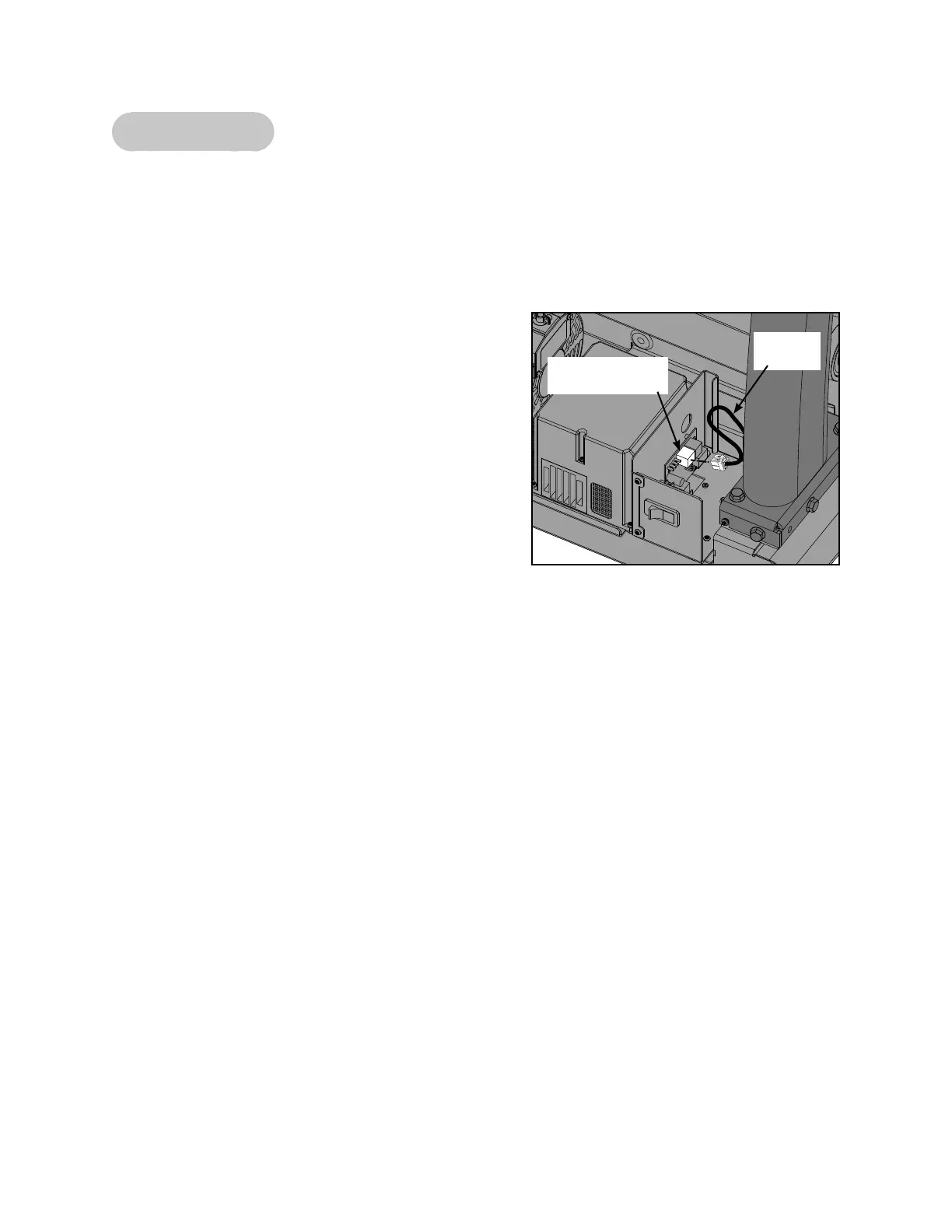
A. Disconnect the display cable from the hub board
connector J3 in the base. See Figure 34.
B. Disconnect the display cable from the display
board. See Figure 25.
C. Pull the display cable out of the console upright.
17. Attach the new display cable.
A. Push the new display cable down through the
console upright and out the bottom hole.
B. Plug the display cable into the hub board
connector J3 in the base. See Figure 34.
C. Plug the display cable into the display board. See
Figure 25.
18. Connect the cables.
A. Connect these cables to the display board: the upper to lower display cable, RJ-45 cable,
handset board cable, display cable and the fan cable. See Figure 25.
19. Check the connections.
A. Check to see that all of the cables are connected firmly in their proper place.
20. Install the console back to the upright assembly.
A. Locate the back cover and nine screws.
B. Place the back cover in the correct position on the console assembly. See Figure 23.
C. Using a Phillips screwdriver, install the nine screws securing the back cover to the console
assembly. See Figure 24.
21. Secure the motor cover.
A. Place the motor cover in position the treadmill by locating the tabs in the correct locations. See
Figure 7. NOTE: If motor cover does not fi t properly, loosen the front and side cover screws as
needed.
Figure 34
Display
Cable
Hub Board
Connector J3