Cybex 750T Treadmill Service Manual
Service
Page 4-24
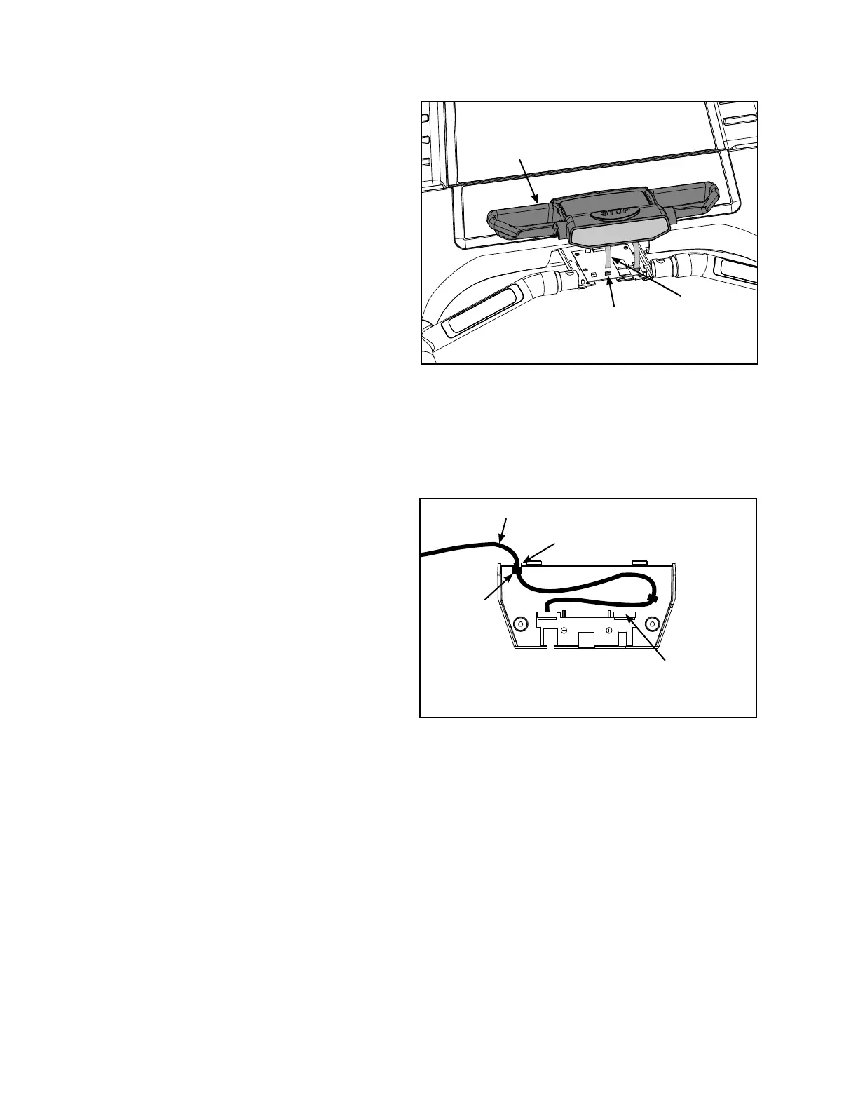
D. Rotate the upper handset cover up and
off handrail.
12. Install upper handset cover.
Place the upper handset cover in position A.
on handrail. See Figure 32.
NOTE: Do not pinch the contact heart rate
cables when installing the handset
assembly top and screws.
Carefully insert the ribbon cable(s) into B.
the handset board.
C. Place the lower handset cover in
position. See Figure 31.
D. Using a Phillips screwdriver, install four
screws that secure lower handset cover to
the upper handset cover. See Figure 31.
NOTE: For Non-AV units skip to step 14.
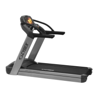
13. Install AV cables into lower cover.
Plug the iPod cable into the left side of A.
the lower cover. See Figure 33.
Route the B. iPod cable through the notch
in the lower cover. Ensure the second
strain relief is used to expose cable to
shortest length. See Figure 33.
NOTE: Ensure the iPod cable remains in the
notch of the lower handset cover and the
green composite cable is not pinched
during the next step.
14. Install lower cover.
Using a Phillips screwdriver, secure the A.
lower cover to the lower handset cover
using the two screws removed in step
10A. See Figure 30a (Non-AV units) or Figure 30b (AV units).
15. Install e-stop.
Clip lanyard onto storage tab on lower cover and plug e-stop into console. See Figure 29.A.
Figure 33
iPod Cable
Green
Composite
Cable Connector
Strain
Relief
Notch
Figure 32
Connector
(Handset
Board)
Ribbon
Cable
Upper
Handset
Cover