EN / CZone® DDS User & Installation Manual
PLANNING
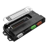
Make a list of all inputs and outputs to be wired to the DDS and take note of the output channel ratings and input channel
functions as shown in the tables below. Assign each input and output to a channel on the DDS, ensuring loads are wired
to the appropriate channel rating and function.
• Relay Output – Relay switched output channels, suitable for general loads, take note of current rating for
each channel on 12V and 24V systems.
• MOSFET Output – MOSFET driven outputs can be set to ON/OFF or Pulse Width Modulation (PWM) mode
to dim lights during configuration. Inrush current will need to be kept below 130% of maximum channel
current.
• Signal Input – 0-30V or 0-1000ohm, e.g. 0-5V Sender, 10-180ohm Sender, 240-33ohm Sender.
• Switch Input – Switch Inputs, take note of channel POS or NEG support.
• Digital Output –
o Up to 150mA output driving unsuppressed inductive loads. E.g., relay coil.
o Up to 250mA output driving non-inductive loads such as indicators, control circuits etc. (Relay coils up
to 250mA require the addition of a freewheeling diode)
• System Ground – Required to be grounded to vessel/vehicle common ground.
• Power Output – 24 hour fused output for positive input channels.
• Ground – Common ground for switch to NEG references or status LED grounds.
PIN # Function
A1,
A12
20A Relay Output 1 (Both pins required to be
paralleled for loads over 10A)
A2,
A11
20A Relay Output 2 (Both pins required to be
paralleled for loads over 10A)
A3 10A Relay Output 1
A8 5A Relay Output 2
B1 2A Relay Output 1
B6 System Ground
B11 2A MOSFET Output 2
C1 Switch Input 1 (POS/NEG)
C6 Power Output
Digital Output 5 (POS/NEG)
Digital Output 4 (POS/NEG)
Digital Output 3 (POS/NEG)
C11 Digital Output 2 (POS/NEG)
Digital Output 1 (POS/NEG)
D2 Switch Input 7 (POS)
D7 Ground
D12 Digital Output 6 (POS)