EN / CZone® DDS User & Installation Manual
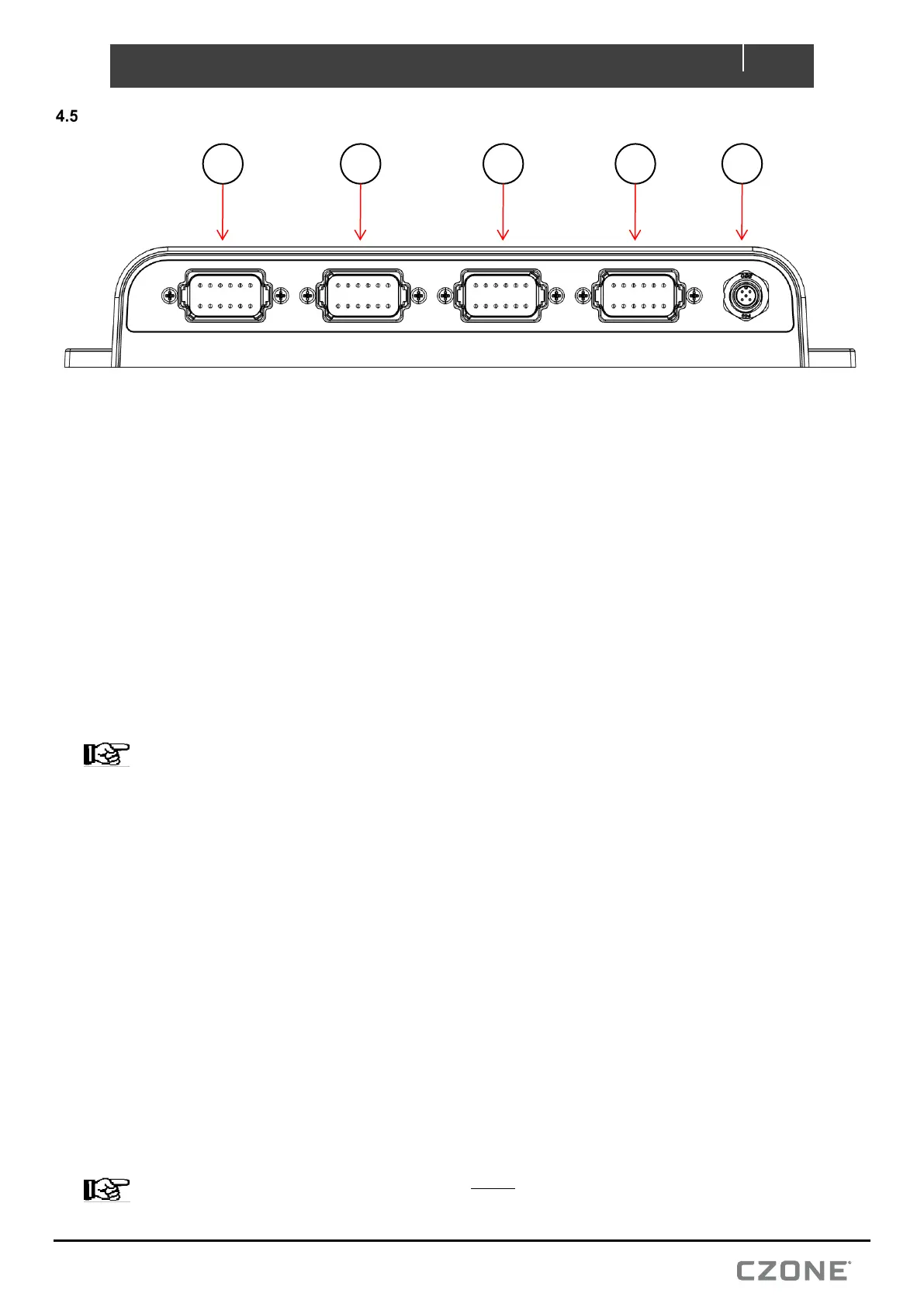
CONNECTIONS
1. Connector A consists of 10x positive relay outputs. Carefully check each required load against the table
above taking into consideration the relay channel ratings.
1. Referring to the load list, strip and crimp the output channel cables with the appropriate Amphenol contact
and crimp tool.
2. Insert the contacts into the AT06-12SA plug following the plugs position numbers and secure using the
locking wedge.
3. Any unused pins in the connector should be plugged with sealing plugs to maintain the IP65 rating.
(Amphenol Part # A114017).
4. Before inserting the connector it’s highly recommended to apply a small amount of silicone grease along
the sealing surfaces/gasket. This will make assembly/disassembly easier.
5. Insert the connector into the DDS until it clicks into place.
6. Secure and neaten up the cables against the bulkhead to reduce the strain on the connectors.
NOTE – For 20A relay channels 1 and 2, if the connected load exceeds 10A both pins of the channel must
be connected in parallel to the load. Both legs of the channel require external 10A fuses fitted before they
parallel together. Both channel output pins will be live with output turned on, if only one pin is required, a sealing
plug (Amphenol Part # A114017) should be inserted into unused pin.
2. Connector B consists of 2x positive relay outputs, 5x MOSFET outputs, 3x analog inputs and the system
ground inputs. Carefully check each required load/input against the table above taking into consideration
channel function and limitations.
1. Referring to the load and analog input list, strip and crimp the cables with the appropriate Amphenol contact
and crimp tool.
2. Insert the contacts into the AT06-12SB plug following the plugs position numbers and secure using the
locking wedge.
3. Any unused pins in the connector should be plugged with sealing plugs to maintain the IP65 rating.
(Amphenol Part # A114017).
4. Before inserting the connector it’s highly recommended to apply a small amount of silicone grease along
the sealing surfaces/gasket. This will make assembly/disassembly easier.
5. Insert the connector into the DDS until it clicks into place.
6. Secure and neaten up the cables against the bulkhead to reduce the strain on the connectors.
NOTE – System Ground inputs on Connector B MUST be connected to vessel/vehicle common ground.
Figure 8. Connections
5