EN / CZone® DDS User & Installation Manual
3. Connector C consists of 5x Pos/Neg switch inputs and 5x Pos/Neg 250mA digital outputs. Carefully check
the channel limitations in the table above.
1. Referring to the switch input and digital output list, strip and crimp the cables with the appropriate Amphenol
contact and crimp tool.
2. Insert the contacts into the AT06-12SC plug following the plugs position numbers and secure using the
locking wedge.
3. Any unused pins in the connector should be plugged with sealing plugs to maintain the IP65 rating.
(Amphenol Part # A114017).
4. Before inserting the connector it’s highly recommended to apply a small amount of silicone grease along
the sealing surfaces/gasket. This will make assembly/disassembly easier.
5. Insert the connector into the DDS until it clicks into place.
6. Secure and neaten up the cables against the bulkhead to reduce the strain on the connectors.
4. Connector D consists of 5x switch inputs (positive only) and 5x 250mA digital outputs (positive only).
Carefully check the channel limitations in the table above.
7. Referring to the digital input and digital output list, strip and crimp the cables with the appropriate Amphenol
contact and crimp tool.
8. Insert the contacts into the AT06-12SD plug following the plugs position numbers and secure using the
locking wedge.
9. Any unused pins in the connector should be plugged with sealing plugs to maintain the IP65 rating.
(Amphenol Part # A114017).
10. Before inserting the connector it’s highly recommended to apply a small amount of silicone grease along
the sealing surfaces/gasket. This will make assembly/disassembly easier.
11. Insert the connector into the DDS until it clicks into place.
12. Secure and neaten up the cables against the bulkhead to reduce the strain on the connectors.
NOTE – Connector D digital inputs are ‘Switch to POS’ only and digital outputs are 250mA POS output only.
5. Connect NMEA2000 network
1. Connect a NMEA2000 drop cable from the DDS to the vessel/vehicle NMEA2000 backbone.
2. Ensure the NMEA2000 network is properly terminated and connected to a 12V power source (Do not
power up network yet).
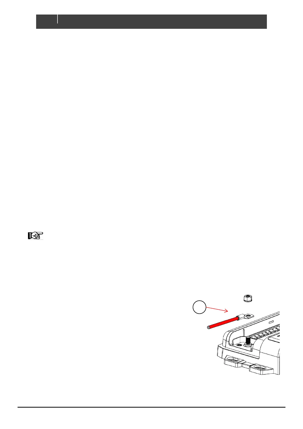
6. Connect DC Positive
1. Connect an appropriately sized and fused cable from the battery
positive terminal to the DDS’s M8 positive stud.
2. The positive cable must be of sufficient size to carry the
maximum current of all loads connected to the DDS and have a
fuse/circuit breaker rated to protect the cable, volt drop should
be kept to a minimum.
3. Maximum recommended cable size is 50mm² (1/0 AWG).
Cables larger than 50mm² (1/0 AWG) should be connected to a
joiner stud first with a link to the DDS.
4. Ensure the M8 nut is torqued to 3.9Nm (34.5in/lbs.).
Figure 9. Positive Terminal