70D-Link DCS-5222L User Manual
Appendix A - Technical Specications
Technical Specications - I/O Terminal Applications
The digital input/output port is typically used in association with programming scripts for developing applications for motion detection, event triggering,
alarm notication via e-mail, and a variety of external control functions. The 4-pin I/O Terminal Block is located on the rear panel and provides the
interface of a photo-coupled switch output and a photo-coupled input.
Connector Pin Assignment
Sign FUNCTION SPECIFICATION
DO- Photo-Relay OUTPUT (Normal Open) Close circuit current max. 70 mA AC, or 100 mA DC.
On-Resistance max. 30 Ohm.
Open circuit blocking voltage max. 240VAC or 340VDC
DO+ Photo-Relay OUTPUT(Common)
DI- Photo-Relay INPUT (-) Active High voltage 2.5~25VDC
Inactive Dropout voltage 0~1.5 VDC
Internal on-current has limit at 7mA
to protect the photo-relay.
DI+ Photo-Relay INPUT (+)
Monitoring and Controlling
By entering http requests in your browser’s URL eld, it is possible to:
• Monitor the status of digital input.
• Turn the output switch on or o.
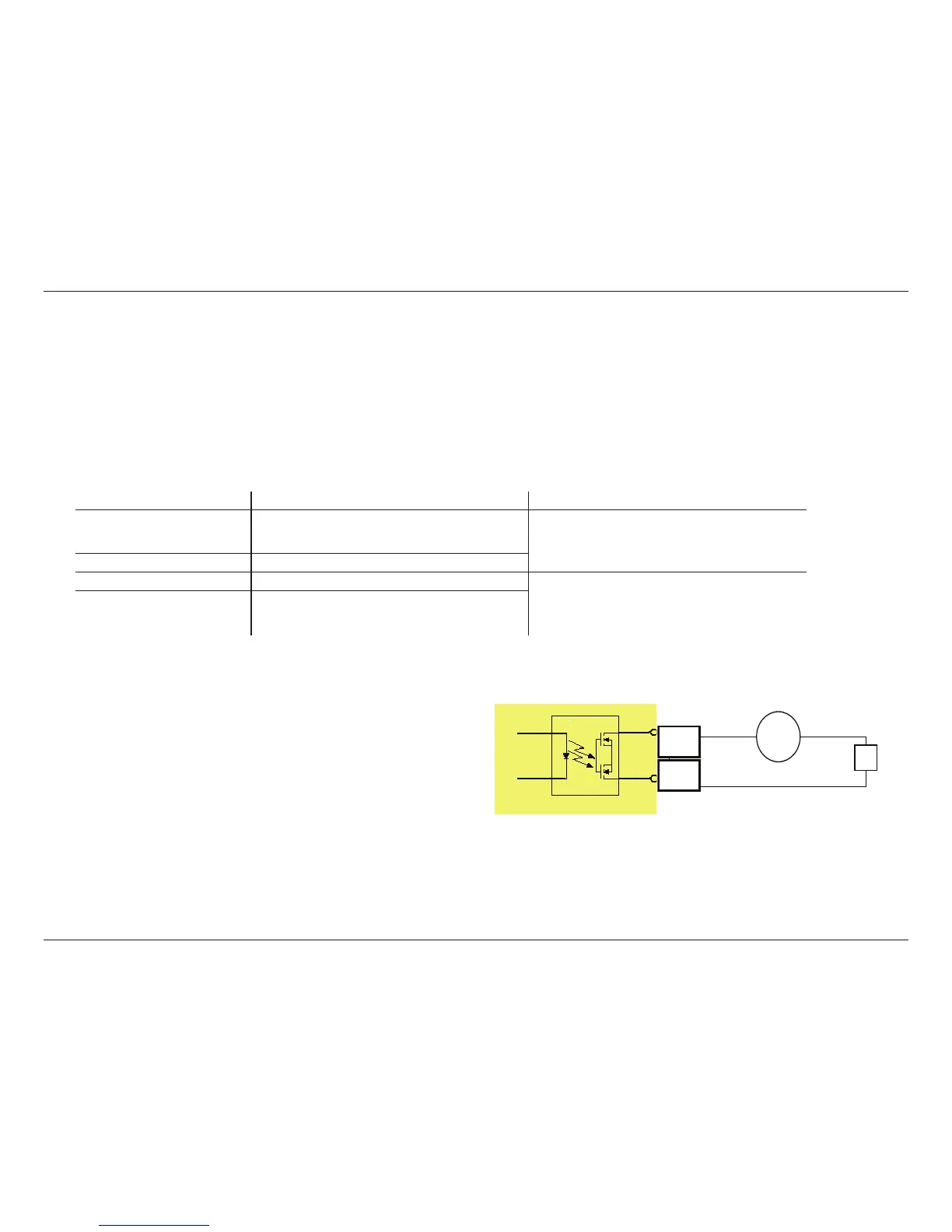
Interface Schematic
Output device (load) is driven by an external AC or DC power supply.
Input device (active control device) has an independent power supply.