1 Product Introduction D-Link Web Smart Switch User Manual
6
Front Panel
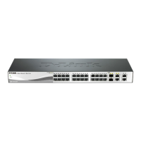
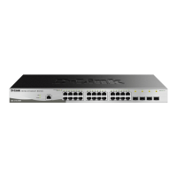
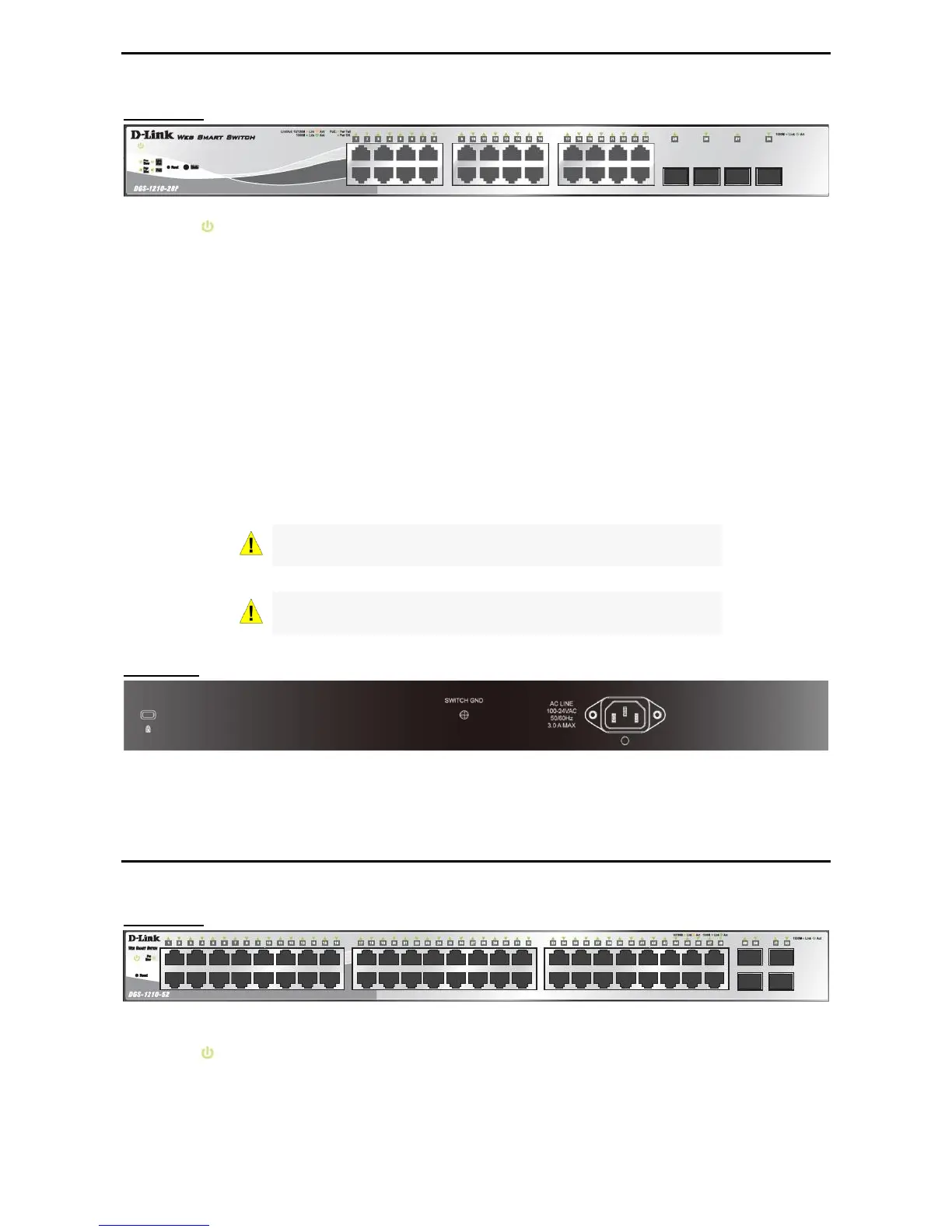
Figure 1.9 – DGS-1210-28P Front Panel
Power LED : The Power LED lights up when the Switch is connected to a power source.
Fan Error: The Fan Error lights up with solid red when the fan has runtime failure and is brought offline.
Pwr Max: The Pwr Max LED lights up with solid red when the Switch reaches the maximum power budget
defined by the administrator via PoE System Settings page of Web GUI or the default power budget of 193
Watts.
Reset: By pressing the Reset button for 5 seconds, the Switch will change back to the default configuration
and all changes will be lost.
Mode: By pressing the Mode button, the Port LED will switch between Link/Act and PoE modes.
Port Link/Act/Speed LED (1-24): The Link/Act/Speed LED flashes, which indicates a network link through
the corresponding port. Blinking indicates that the Switch is either sending or receiving data to the port.
When a port has an amber light, this indicates that the port is running on 10M or 100M. When it has a green
light it is running on 1000M.
Port Link/Act/Speed LED (25F, 26F, 27F, 28F): The Link/Act/Speed LED flashes, which indicates a
network link through the corresponding port. Blinking indicates that the Switch is either sending or receiving
data to the port. When a port has a green light, this indicates that the port is running on 1000M.
Rear Panel
Figure 1.10 – DGS-1210-28P Rear Panel
Power: Connect the supplied AC power cable to this port
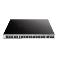
DGS-1210-52
48-Port 10/100/1000Mbps plus 4 SFP Slot Web Smart Switch.
Front Panel
Figure 1.11 – DGS-1210-52 Front Panel
Power LED : The Power LED lights up when the Switch is connected to a power source.
Fan Error: The FAN LED shows the status of the fans, light off indicates all fans work fine and the red light
indicates that one or multiple fans are working abnormally.
Port Link/Act/Speed LED (1-48): The Link/Act/Speed LED flashes, which indicates a network link through
the corresponding port. Blinking indicates that the Switch is either sending or receiving data to the port.
 Loading...